How Do I Add an External Communicator to a DSC PowerSeries NEO?
You can add an external communicator to a DSC PowerSeries NEO by completing all the connections between the panel, the communicator, and the PCL-422 module. You should have the system powered down during the installation. You can activate the communicator for monitoring once it is wired.

The DSC PowerSeries NEO needs an external communicator for alarm monitoring service and connectivity with Alarm.com. The system has a series of dual-path communicators available. These dual-path communicators use LTE cellular connectivity and IP connectivity through a wired ethernet cable to communicate with the Alarm.com servers. Per Alarm.com requirements, the cellular portion of the communicator must be activated and registered. The IP portion is technically optional, but there isn't really any disadvantage to setting up internet connectivity to serve as an additional communication path. Some of the most popular communicator options for the DSC PowerSeries NEO include the DSC TL880LEAT N AT&T LTE & IP Communicator and the DSC TL880LTVZ N Verizon LTE & IP Communicator. Both represent a great option when upgrading a DSC PowerSeries NEO to use LTE.
An external communicator for the NEO will draw power from the panel. It will not use its own transformer or backup battery. During an alarm state, the communicator will draw up to 400mA of power from the panel. Make sure your NEO System has enough available current to power the communicator, as well as all of the other connected devices for the system. For reference, the NEO can provide a maximum of 700mA of power, with DSC recommending that the load not exceed 650mA. If you find that adding a communicator will push the system over the recommended load limit, then you can add an external power supply to provide additional power. The DSC HSM2300 can be used very well for this task. An external power supply will use its own transformer and battery.
When installing a communicator for a DSC PowerSeries NEO, there are three (3) components to consider. These are the NEO Panel, the communicator, and the DSC PCL-422 Remote Communicator Module. The communicator and the DSC PCL-422 have six (6) wired connections in total. The DSC PCL-422 then connects with the panel using the included PC-Link Cable. Nothing connects directly between the communicator and the panel. Everything goes through the DSC PCL-422 in some manner. The DSC PCL-422 is typically mounted inside the same metal enclosure as the panel, usually on the side. The communicator is mounted elsewhere, in an area where a strong cellular signal can be achieved. The antenna for the communicator should be positioned to give as strong a cellular signal as possible. For this FAQ, we will assume that the DSC PCL-422 is already mounted inside the panel's enclosure.
Although mounting hardware and the PCL-422 all come included with the communicator, you must still provide your own wiring. We recommend using 18-AWG, 4-conductor cabling to complete the installation process. However, you can certainly use slightly thicker or thinner wire if that's what you have on hand. Please note that the maximum wire run distance between the PCL-422 and communicator is 100 feet when 18-AWG cabling is used. Remember to run wires through the respective back plates of the panel and the communicator. Otherwise, you won't be able to properly close everything when you are finished. We find that stranded alarm wire is the easiest to work with.
Complete the following steps to add an external communicator to a DSC PowerSeries NEO:
1. Enable the programming field. On most systems, the first step when installing a communicator is to power down the system. But for the NEO, it's a little bit different. DSC recommends enabling the programming field for the communicator prior to the installation. This way, the system can boot up with the communicator enabled.
Using an alphanumeric keypad, enter the command [*] + [8] + [Installer Code] to enter programming. The default Installer Code for the system is 5555. Then enter the programming field [382]. Use the arrow keys (< & >) to scroll to Option (5) for "Alternate Comm". Use the [*] key to toggle the selection to Y for YES. Once it is set to Y, repeatedly press the [#] key to exit programming and return to the main screen.

2. Power down the system. Before making any hardware changes, you should always power down the system. Disconnect the backup battery, and unplug the transformer to power down the system.
3. Open the communicator. When facing the communicator, note the two (2) notches on the left side. Use a flat head screwdriver to push in the two tabs. You should then be able to easily pull off the communicator front cover.


4. Note the IMEI number. Now is a good time to note the IMEI number for the communicator. You will need this information later on when activating the communicator with Alarm.com. The IMEI number can be found on a white sticker on the green circuit board inside the communicator. We recommend carefully writing down the IMEI number or taking a picture of the code. Store the IMEI number in a safe location for whenever you need to access it.
5. Mount the communicator. Before wiring, it is a good idea to mount the communicator. Make sure to choose an area where a strong cellular signal can be obtained. Mounting hardware for the communicator comes included. You will need to drill holes for the wall anchors and screws. The back of the communicator enclosure will be secured to the wall. Its front cover can be easily seated when installation is complete. Remember to make a hole in the wall for you to run wires through the back of the communicator. You can loosely mount the antenna for now, as you will be adjusting its position later.
6. Connect communicator to PCL-422. For this FAQ, we are assuming that the PCL-422 is already mounted inside the panel on the side of the enclosure. Use the plastic stand offs included, and connect through the pre-made holes in the right side of the metal enclosure. There will be a total of six (6) connections between the communicator and the PCL-422. There is a 4-wire connection for data transmissions, as well as a separate 2-wire connection to supply power to the communicator. Remember to run the wires through the back plates of both the communicator and the panel. Remember that the maximum wire run distance between the PCL-422 and communicator is 100 feet when 18-AWG cabling is used.

For the 4-wire connection for data transmissions, the following connections are made:
- TX+ Terminal on PCL-422 to RX+ Terminal on Communicator
- TX- Terminal on PCL-422 to RX- Terminal on Communicator
- RX+ Terminal on PCL-422 to TX+ Terminal on Communicator
- RX- Terminal on PCL-422 to TX- Terminal on Communicator
For the 2-wire connection for power, the following connections are made:
- GND Terminal on PCL-422 to GND Terminal on Communicator
- +12V Terminal on PCL-422 to +12V Terminal on Communicator
7. Connect PCL-422 to panel. You will now use the PC-Link Cable to connect the PCL-422 to the panel. The PC-Link Cable is a 5-wire cable, that is female on both ends. You connect either end to the male 5-prong PC Link Port on the PCL-422. The other end will connect with the identical male 5-prong PC Link 2 Port on the PowerSeries NEO Panel. Make sure to use PC Link Port Number 2 on the NEO Panel. Do not use PC Link Port Number 1.


When connecting to PC Link Port Number 2 on the panel, the red wire should be positioned on the right-hand side when facing the NEO Panel. In other words, the red wire will be on the opposite end from PC Link Port Number 1. Conversely, the connection at the PCL-422 will have the red wire positioned on the left-hand side when facing the PCL-422. This will position the red wire at the bottom when the PCL-422 is mounted inside the panel normally. Another way to consider this is that the red wire on the PCL-422 will be on the side closest to the screw terminals.


8. Connect the ethernet wire. If you plan to use IP connectivity with the communicator, then you must run an ethernet cable from your internet router to the communicator. This is optional, as a DSC PowerSeries NEO Communicator can register with Alarm.com through cellular only.
It is also possible to have the communicator speak wirelessly with an IP router by using an ethernet to WIFI bridge. A good ethernet to WIFI bridge to use is the Alarm.com ADC-W110. If you do this, then you will run an ethernet wire between the communicator and the ethernet to WIFI bridge. The WIFI bridge will be plugged into a power outlet. You must then configure the ethernet to WIFI bridge to work on your WIFI network. Remember that the ethernet to WIFI bridge will lose power in the event of an AC Power outage. When that happens, your alarm system will be relying on cellular communication until AC Power is restored.
9. Close the communicator. You can now close the cover for the communicator. Secure the end opposite from the two notches that are used when opening the module. Then click the two notches securely into place.
10. Power on the system. Now that all the connections are made, you can power the system back on. Connect the backup battery first, then the transformer.
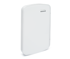
11. Position the antenna. You will now be positioning the antenna for the communicator. The goal is to achieve the strongest cellular signal possible for your area. You can check the cell signal for the communicator by looking at the flashing green LED light on the communicator. This is the second LED light from the right when facing the module, and it is the only green LED on the module.
Cell signal is expressed by the number of consecutive flashes made by the LED. The greater number of flashes, the stronger the cell signal. A total of five (5) flashes indicates the strongest cell signal, while zero (0) flashes indicates that absolutely no cellular signal is obtained. You need a minimum of two (2) flashes to successfully connect with Alarm.com. However, we strongly recommend achieving at least three (3) flashes.
Try positioning the antenna in different places to see if a certain mounting spot provides a stronger cellular signal. Once you have found the optimal location for the antenna, secure it to that location. If you are having trouble achieving an adequate cellular connection, try mounting the communicator in a different location, or try using a cellular antenna or a cellular amplifier to boost the cellular signals.
12. Activate the communicator. From here, the activation process will be handled by your alarm monitoring company. You will be required to provide the IMEI number for the communicator during the activation. If you are setting up service with Alarm Grid, then an activator will contact you at your scheduled activation time. Remember that you will need to sign-up for a monitoring plan that includes cellular service and access to Alarm.com. If you want to learn more about Alarm Grid monitoring plans, then please check out this post. Also check out these tips to ensure that your Alarm Grid activation goes smoothly.
Did you find this answer useful?
We offer alarm monitoring as low as $10 / month
Click Here to Learn MoreRelated Products


Related Videos

Related Categories
- LTE Cellular Communicators
- Verizon LTE Cellular Communicators
- LTE Cellular Communicators
- Dual-Path Alarm Communicators
- AT&T LTE Cellular Communicators
- Answered