How Do I Install a Honeywell LTE-XA or LTE-XV On a VISTA-15P, 20P, or 21iP?
You can install a Honeywell LTE-XA or LTE-XV on a VISTA P-Series Panel by completing the necessary 4-wire connection and mounting the communicator to the wall or outside the panel's metal enclosure. You should check the cellular signals before determining a permanent mounting location.
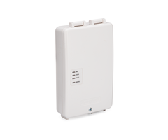
The Honeywell LTE-XA and LTE-XV are LTE cellular communicators built for Honeywell VISTA Series Alarm Panels. They allow the panel to communicate with the Resideo AlarmNet360 Servers for monitoring service. The user will need a compatible monitoring plan to activate the communicator. Examples of compatible monitoring plans include the Alarm Grid Gold and Platinum Plans (Self or Full) and the Alarm Grid Cellular-Only Plan. The communicator should be activated for monitoring service after it has been installed.
Since these are AlarmNet Communicators, they will allow the connected system to be used with Total Connect 2.0. This is an interactive monitoring and automation platform that can be used to remotely access and operate the system. You can use Total Connect 2.0 to arm/disarm, check system status, control automation devices, and more. The service can be accessed using a web browser or a mobile app on a phone. In order to use the Total Connect 2.0 service, it must be included in your monitoring plan. You must also make sure that your VISTA System is running a high enough firmware version.
The firmware version of a VISTA System is determined by its PROM Chip. This is a small black chip on the main board for the system. A VISTA-15P or VISTA-20P System will need Firmware Version 9.12 or higher. A VISTA-21iP System will need Firmware Version 3.13 or higher. A VISTA-10P System cannot use Total Connect 2.0 on any firmware version. But you can still use a VISTA-10P with an LTE-XA or LTE-XV Cellular Communicator for basic monitoring service. If you want more information on replacing a PROM Chip, please review this FAQ. Note that Alarm Grid sells PROM Chips for 15P, 20P, and 21iP Systems.
There is one important note about using an LTE-XA or LTE-XV with a VISTA-21iP or VISTA-21iPLTE Panel. These systems require you to disable the built-in IP communicator for the panel before an external cellular communicator will work. More information on this can be found in this helpful FAQ. Please note that if you have a Honeywell VISTA-21iPLTE System, then it is strongly recommended that you get a Honeywell LTE-21V Communicator instead of an LTE-XA or LTE-XV Communicator.
This FAQ assumes that you are mounting the communicator to the outside of the panel's metal enclosure. If you are mounting the communicator to the wall, then you will need to run the connector wire accordingly. Complete the following steps to install a Honeywell LTE-XA or Honeywell LTE-XV Communicator on a Honeywell VISTA P-Series System:
1. Test signal strength. You should first determine if the area where you are intending to use the communicator will allow the module to achieve adequate cellular signal strength. You can temporarily power the communicator using a 12V battery. Or you can use power from the panel to power the module.
If you want to use the panel power to test the module, start by powering down the panel completely. This is done by disconnecting the transformer and the backup battery for the system. Then connect the black wire from the module's harness to Panel Terminal 4 and the red wire from the module's harness to Panel Terminal 5. You can leave the yellow and green wires disconnected for now. Then power the panel back on. Wait a few moments, and the LED signal on the LTE-XA or LTE-XV should power on. If the LED is solid green, then you have adequate signal. If not, then you might consider using the communicator in a different location, or you can add a cellular antenna or a cellular amplifier to boost the signals.

2. Mount the communicator. The communicator can be mounted to a wall using zip-it anchors or wall anchors. However, it is recommended that you mount the communicator on the outside of the metal cabinet for the panel. You should start by knocking out the round indented spot on the upper-right corner of the metal cabinet. This is where the LTE-XA or LTE-XV will be mounted. A metal washer comes included for securing the communicator.

A threaded plastic hole-cap will need to be secured to the LTE-XA or LTE-XV. This is the part of the communicator that connects with the knock-out hole on the metal cabinet. The image below shows the threaded hole-cap secured into place. Make sure the hole-cap "snaps" into place when securing it.

Take the LTE-XA or LTE-XV with the plastic hole-cap secured and insert it into the hole you knocked out of the metal cabinet. Then use the metal washer to secure the communicator in place. Please note that you will be running the ECP wiring through this hole. You can see more in the diagram below.

3. Make the connections. Start by powering the system completely down if it isn't already. The system is powered down by unplugging the panel's transformer and disconnecting the backup battery. Use the included wiring harness for the communicator and connect it with the part labeled ECP cable in the above diagram. Then run the connecting wires down through the hole-cap to where the main panel is located. You will be using Panel Terminals 4 through 7 for the connections. The connections are as follows:
- The Black Wire is for negative (-) power. It goes to Terminal 4.
- The Red Wire is for positive (+) power. It goes to Terminal 5.
- The Green Wire is for data from the communicator to the panel. It goes to Terminal 6.
- The Yellow Wire is for data from the panel to the communicator. It goes to Terminal 7.

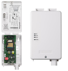
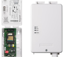
4. Activate the communicator. Once you have finished connecting the communicator, you should first power your system back on. Plug in the transformer before connecting the backup battery. You will need to activate the communicator for monitoring service. This process is completed by your monitoring company. You will need to provide them with the MAC and MAC CRC of your LTE communicator. These can be found on a white sticker mounted on one of the green circuit boards inside the communicator.
If you are a new Alarm Grid customer, you will have selected an activation slot during the sign-up process. An activator will call you at that time to complete the process. Please have the above steps completed before this happens. We have activation slots available from 9am to 8pm ET Monday through Friday.
If you are an existing Alarm Grid customer upgrading your VISTA P-Series Panel to use LTE, then you should email us at support@alarmgrid.com, and we will work with you to determine the best time to complete the upgrade. Remember that our available support hours are from 9am to 8pm ET Monday through Friday.
Did you find this answer useful?
We offer alarm monitoring as low as $10 / month
Click Here to Learn MoreRelated Products
Related Videos

Related Categories
- Answered