How Do I Install the Resideo LTE-IV On My VISTA P-Series System?
You can install the Resideo LTE-IV on your VISTA P-Series System by testing its signal strength, mounting the module, powering down the VISTA Panel, providing power to the communicator, connecting the module to the panel, powering the VISTA Panel back on, and programming the communicator.
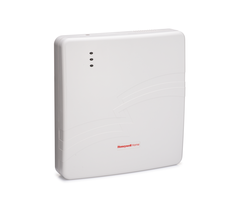
The Resideo LTE-IV is a dual-path communicator for the VISTA P-Series Systems and VISTA Turbo Series Panels. This communicator works across the Verizon LTE Network and a local IP network. The module uses a hardwired ethernet connection for IP connectivity. For the VISTA P-Series Systems, the LTE-IV will work as an alarm communicator with any VISTA 10P, VISTA 15P, VISTA 20P, or VISTA 21iP.
If you want to use Total Connect 2.0 with the Resideo LTE-IV, you will need a VISTA 15P or 20P running Firmware Version 9.12 or higher, or a 21iP must be running Firmware Version 3.13 or higher. A VISTA 10P System cannot be used with Total Connect 2.0. The Firmware Version can be found on the PROM Chip for the system. This is a small black chip found on the panel's main board. It should have a sticker that lists the manufacture date and the revision number. If you need to upgrade the PROM Chip for your VISTA System, please check this FAQ.
Complete the following steps to install the Resideo LTE-IV on your VISTA P-Series System:
1. Test the signal strength. You should test the signal strength for the LTE-IV before mounting it to the panel. To do this, have the LTE-IV positioned next to the VISTA Panel. Connect the AC transformer and the backup battery for the LTE-IV. The module should power on. Check the LED lights on the device to determine the signal strength. Three (3) or more LED lights (two (2) Yellow, and one (1) Green) indicate that the unit is receiving adequate signal strength. Your monitoring company will be able to conduct a more accurate test of signal strength once the unit is registered.

2. Mount the device. The LTE-IV is a lightweight communicator that can be easily mounted to the wall. You can use zip-it anchors or the included wall anchors to complete the mounting process. When doing this, make sure to line up the back plate on the wall and mark the keyholes until the unit is nice and level. The wall anchor should slide in snugly. Then secure the screws. Make sure to leave space for the wall plate to sit on before you tighten the screws. Then rest the back plate on the screws, and tighten the screws to secure the device.
3. Power down the panel. You will want to power down your VISTA Panel before continuing. You can do this by disconnecting the backup battery and unplugging the transformer. Any keypads used with the system should go blank, and no lights should be present on the system board. Any keypads powered by a secondary power supply will display "Open CKT", "OC" or "ECP Error" during this time.
If you are adding an LTE-IV to an older VISTA-21iP panel, you will need to disable the internal communicator in the panel. This is because the panel can support either an external communicator or an internal communicator, but not both. While the system is powered down, find the jumper marked "Internal IP/GSM Jumper" and move it to the bottom two pins. This removes power from the internal communicator, allowing you to add an external LTE communicator. If you wish to use Total Connect 2.0, be sure the Vista-21iP panel is at least version 3.13 or higher. If the panel is an older version, upgrade the entire system to a VISTA-21iPLTE, which supports a snap-in LTE communicator.

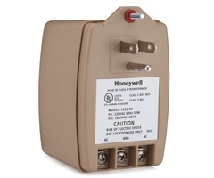
4. Power the device. The LTE-IV uses a Honeywell 1361 Transformer for primary power. You can have this transformer power just the communicator, or you can use it to power both the communicator and the Vista-P panel.
If you are using the 1361 to power just the LTE-IV, then connect the transformer to Terminals 1 and 2 on the communicator. Since this is an AC transformer, polarity does not matter, and either wire from the transformer can go to either Terminal 1 or 2 on the communicator. From there, you should connect Terminal 3 (ECP+) on the communicator to Terminal 5 (AUX+) on the panel. Connect Terminal 4 (GND) on the communicator to Terminal 4 (GND) on the panel. Next, connect the data wires. Wire Terminal 6 (Data Out) on the LTE-IV to Panel Terminal 6 (Data In). Lastly, connect LTE-IV Terminal 5 (Data In) to Panel Terminal 7 (Data Out). Plug in the transformer when you are finished.
If you want to use the 1361 to power both the panel and the LTE-IV, then you should start by removing the existing transformer. Unplug the transformer and disconnect the two (2) wires from it. Connect those wires to the 1361 instead. Then connect Terminals 1 and 2 on the VISTA Panel to Terminals 1 and 2 on the LTE-IV. This will let the LTE-IV share the connection with the transformer that powers the VISTA Panel. Terminal 3 on the LTE-IV (ECP+) should connect with Terminal 5 on the Panel (AUX+). Terminal 4 on the panel (GND) should connect with Terminal 4 on the LTE-IV (GND). Terminal 7 on the panel (Data Out) should connect with Terminal 5 on the LTE-IV (Data In). Terminal 6 on the Panel (Data In) should Connect with Terminal 6 on the LTE-IV (Data Out). All of this can be seen in the diagram below:

5. Provide backup power. You will then want to provide a backup power source for the communicator. The LTE-IV comes with a 6VDC 3.1Ah battery for backup power. This battery can be placed in the lower-right side of the back plate. You should secure the retainer clip to the back plate to keep the battery in place. The red and black spade connectors should go to the matching battery terminals. The battery can plug into the J1 battery port on the main board for the LTE-IV.
6. Connect the ethernet cable. Run an ethernet cable from your IP router or switch to the LTE-IV module. The cable will connect with the RJ45 port on the LTE-IV. This can be seen in the picture below:

7. Restore panel power. You can now restore power to the VISTA Panel. If you are using the same transformer for the VISTA and the LTE-IV, you can plug that in now. Otherwise, plug in the transformer that is being used to power the VISTA System. Then reconnect the backup battery to the system. Next, plug in the transformer being used to power the LTE-IV. Give the system a few moments to power back on. If any faults are displayed on the keypad, try doing a disarm with the command [Master Code] + [1]. Remember, you will get a tamper cover trouble if the cover is off the LTE-IV. You can keep this off if you are still testing the module. Just remember that you must replace the cover and then enter the disarm command shown above to clear the trouble message from the keypad. You must do this before you will be able to arm the system.
8. Activate the LTE-IV. You will now need to activate the LTE-IV. This involves registering the module with the Resideo AlarmNet Servers. You should contact your alarm monitoring company to complete the activation. Remember that Alarm Grid offers monitoring plans that can be used to activate the LTE-IV and provide you with access to Total Connect 2.0. You will need a Gold Plan or higher (Self or Full) to use this module for cellular communication. If you intend to use the LTE-IV for IP only, then you can use a lower-leveled monitoring plan. More information can be found on our alarm monitoring page.
Did you find this answer useful?
We offer alarm monitoring as low as $10 / month
Click Here to Learn MoreRelated Products


Related Videos

Related Categories
- Answered