How Do You Manually Control an Output On a VISTA-15P, VISTA-20P, or VISTA-21IPLTE Panel?
You can manually control a programmable output on a VISTA P-Series Panel by entering a command at the keypad. Entering a valid 4-digit code + [#] + [7xx], where xx equals the output number, will turn ON a programmable output. Entering a valid code + [#] + [8xx] will turn OFF an output.

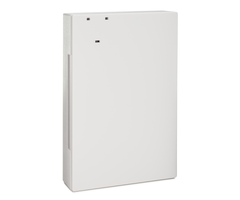
There are two types of programmable outputs that can be used on the VISTA-15P, VISTA-20P, or VISTA-21iPLTE. There is the relay, which can be added to the keypad bus using either a Honeywell 4204, shown above, or by using a Honeywell 4229, which is a combination 8-zone hardwired expander with two (2) Form C programmable relays built-in. The Honeywell 4204 provides four (4) Form C programmable relays. In the normal, or OFF state, either of these types of relays will have continuity between Common and Normally Closed. When active, or ON, either of these types of relays will have continuity between Common and Normally Open. The other type of programmable output is a built-in trigger.
There are two (2) triggers built into each of these panel types. These triggers operate as open collectors. This means that under normal conditions (unless inverted) the trigger is connected to nothing, this is sometimes referred to as floating. When activated, or turned ON, the trigger then connects to ground. This ground connection is common to Terminal 4, and to every zone negative on the panel, with the exception of Zone 1. Trigger 1, known on the panel as Output 17, can provide up to 100 mA of current when used in conjunction with Terminal 5 on the panel. This means the trigger would be acting as the negative, with Terminal 5 acting as the positive. This current is independent of the Auxiliary Power output of 650 mA. Trigger 2, known as Output 18 on the panel, behaves in the same way, but can only provide up to 20 mA of current when used in conjunction with Terminal 5. These triggers can be used for simple things such as sounding a piezo when the panel chimes, or lighting an LED to indicate when the panel is armed.
Relays are usually used in these scenarios to control when power is provided to a device. One example might be if you have sirens that will draw too much current to be powered by the panel itself. In this case, you could add a relay and a power supply and program the relay to turn ON when an alarm occurs, and turn OFF at Bell Timeout, or when the system is disarmed. Generally speaking, if you want to give power to something, you will wire to Common and Normally Open. If you want to take power away from something, you will wire to Common and Normally Closed.
In the example below, Relay 1 on a 4204 is shown wired to provide supplementary power to a series of sirens. In this example, we are controlling the negative leg of power, so you can see that negative from the power supply is connected to Common on Relay 1, and the negative wire for the first siren in line is connected to Normally Open of Relay 1. When Relay 1 turns ON, the circuit is completed and the sirens receive power. When Relay 1 turns OFF, power is removed from the sirens.

An example of the use of the commands to manually activate the relay is to use them to test this setup. You may want to be sure your relay is working, and that all wiring is good, but perhaps you don't want to arm the system and cause a full-blown alarm. In that case you can do the following:
4-Digit Code + [#] + [701] to turn the Relay, and therefore the Sirens, ON
4-Digit Code + [#] + [801] to turn the Relay, and therefore the Sirens, OFF
Now, this example takes a couple of things for granted. First of all, it takes for granted that the programming to map the relay has been completed. This is done in programming location *79. Each device connected to the panel's keypad bus must be addressed, including the 4204 or 4229 when they are being used. The 4229 can use Addresses 07 through 11 while the 4204 can use Addresses 12 through 15. Full information on device mapping and available addresses begins on Page 26 of the VISTA-15P/VISTA-20P Programming Guide.
In our example, we are using a 4204. We are assuming that it is the first or only 4204 in use, and for that reason, we have set it to Address 12. We have our wires connected to Relay 1, so in *79 Output Device Mapping, we chose Output 01 (the name we are giving the relay, and the number we will put after our [#] + [7] or [#] + [8] command shown above). We told the panel that this is a relay, that it is set to Address 12, and that it is Relay number 1 at that address. This is how, when we enter the command above, the panel knows that we want it to turn ON or OFF the Relay that is at Address 12, and Position 1. A total of 18 outputs are available on the VISTA-20P and VISTA-21IPLTE. Outputs 01 - 16 for Relays, and Triggers 1 and 2 at Output 17 and 18. A total of ten (10) outputs are available on a VISTA-15P. Outputs 01 - 08 for Relays, and Triggers 1 and 2 at Output 17 and 18.

To perform this programming via the panel's Alpha Keypad, do the following:
| Key Entries | Information Displayed |
|---|---|
| Installer Code + [8] + [00] | Installer Code 20 |
| [*] + [79] | Enter Output No. 00=Quit |
| [01] + [*] | XX Output Type (where XX indicates Output Number) |
| [1] + [*] | XX Module Address 07 - 15 |
| [12] + [*] | XX Relay Position 1 - 4 |
| [1] + [*] | Enter Output No. 00=Quit |
| [00] | Enter * or # |
| [*] + [99] | Busy Standby - D1 Disarmed Ready to Arm |
To manually control an output, the only programming required is device mapping. There are many other options available to program outputs to activate based on system events, as well as time schedules. The full programming options available for output programming is available starting on Page 28 of the Programming Guide linked above.
Did you find this answer useful?
We offer alarm monitoring as low as $10 / month
Click Here to Learn MoreRelated Products


- Answered
- Answered By
- Julia Ross