How Do I Wire the LTEM-PA or LTEM-PV To Share Panel Power?
The LTEM-PA or LTEM-PV is wired to the panel's auxiliary power terminals, instead of the included DC Transformer. Proper polarity must be observed. Wiring can be achieved using a wiring harness, or the wiring terminals. This configuration will result in only one (1) transformer being used.
Resideo introduced their new LTEM-PA and LTEM-PV dual-path communicators in early 2021. These communicators have a lot of new and different features as compared with similar communicators that were previously released. Some of the new features include a modular design, which allows a variety of different modules to be added to the communicator in support of features like WIFI, WIFI and Z-Wave Plus, or an alternate AT&T LTE or Verizon LTE communicator if the built-in communicator isn't receiving adequate signal, or in the future, when LTE is eventually phased out for a new technology. Another big difference is that for the first time, Resideo has produced a communicator that can work by being connected to the keypad bus of another manufacturer's panel. And the LTEM-PA and LTEM-PV can even allow the other manufacturer's panel to support Total Connect 2.0.
Another big difference with this communicator is that it uses a DC Power Adapter instead of an AC Transformer. With the previously released communicator models, since their transformer is basically the same type used by the alarm panel, users can actually share the transformer between the panel and the communicator. This allows for the use of a single transformer where two would otherwise be necessary. This is helpful because the transformers are big and bulky and it's impossible to plug two of them into a single 2-plug outlet. To make matters worse, in many cases there isn't another outlet available in the vicinity where the panel and the communicator are installed. As a rule, wire runs for power should be kept as short as possible.
The 1361-GT transformer is often used with a Vista-20P or Vista-15P to share the transformer between the communicator and the panel:
![]()
Although the DC transformer used with the LTEM-PA and LTEM-PV is relatively small, the fact that it is DC instead of AC makes a shared transformer configuration impossible. On top of that, in the documentation provided with the LTEM-P Series communicators, no wiring diagram for powering the communicator from the panel's auxiliary power is provided. Since the release of the products and the documentation, Resideo has reversed its position on the question of whether powering the communicator from the panel is possible, even providing guidance on how to properly perform the wiring. However, users should be aware:
This wiring configuration will make the communicator installation non-UL listed. For UL Listed installation, the communicator must be powered by the provided 9VDC Power Adapter only! Most residential alarm systems are not UL certified, this is usually a concern for more complex commercial systems.
Another thing to consider is the available operating current. The Honeywell Vista-15P, Vista-20P, and Vista-21iP panels each have 600 mA of available current on the auxiliary power terminals (Terminal 4 and Terminal 5 for these panels). The Honeywell Vista-128BPT, and VISTA-250BPT each have 750 mA of available current on their auxiliary power terminals (Terminal 6 and Terminal 7). This is the amount of current you have available to power keypads, motion detectors, glass break detectors, expansion modules, and any other devices that require power (not including most polling loop devices on the Turbo panels). This does not include the siren. The siren output has its own current limit and draws most of the required current from the panel's battery in the event of an alarm.
You can see the configurations, and their respective current requirements, for the LTEM-PA and LTEM-PV in the chart below:
| Model and Configuration | Battery Installed | Input Voltage | Active Current |
|---|---|---|---|
| LTEM-PV / PA No Added Modules | Yes | 12 VDC | 263 mA |
| No | 12 VDC | 195 mA* | |
| With PROLTE-V / -A | Yes | 12 VDC | 270 mA |
| No | 12 VDC | 203 mA* | |
| With PROWIFIZW | Yes | 12 VDC | 338 mA |
| No | 12 VDC | 270 mA* | |
| With PRODCM | Yes | 12 VDC | 304 mA |
| No | 12 VDC | 236 mA* | |
| With PROWIFIZW & PRODCM | Yes | 12 VDC | 379 mA |
| No | 12 VDC | 311 mA* | |
| With PROLTE-V/-A & PRODCM | Yes | 12 VDC | 311 mA |
| No | 12 VDC | 244 mA* | |
| With PROLTE-V/-A & PROWIFIZW | Yes | 12 VDC | 345 mA |
| No | 12 VDC | 278 mA* | |
| LTEM-PV / PA + All Modules | Yes | 12 VDC | 386 mA |
| No | 12 VDC | 319 mA* | |
| *Note: If you choose not to connect the communicator battery, you must disable radio Low Battery Reporting | |||
As you can see from the table above, the LTEM-PA or LTEM-PV can draw a considerable amount of current, depending on the configuration being used. If the amount of current needed will exceed what's available from the panel's auxiliary power terminals, you could choose to add an auxiliary power supply such as the Honeywell AD12612, but doing so would require not only another large, bulky transformer but also another battery. In this case, it's just easier to use the communicator's DC Power Adapter and the communicator's included battery.
It is possible to use a heavy-duty power strip connected to the outlet, with the panel transformer and the LTEM-PA or LTEM-PV communicator's DC Power Adapter plugged into the power strip. If you choose to go this route, you should use a nice power strip with over-current protection via a fuse or breaker. Calculate the maximum current that needs to be available for these two devices at 5 Amps, so be sure the power strip is rated to handle at least that much, and that this wiring configuration isn't going to overdraw the breaker for the outlet. Never daisy-chain one power strip off of another, and be sure that the wires for this don't cause a trip hazard, and that they can't be easily unplugged by accident.
If you've come this far and you still want to power the LTEM-PA or LTEM-PV from the panel's auxiliary power terminals, follow these steps:
-
Determine the mounting location. The communicator should be mounted in a location where it can receive a strong cellular signal, assuming cellular service will be used. If WIFI will be used, that should be another consideration. If you plan to power the communicator from the panel, then you'll also want to be mindful of how far you will need to run the wire to get it from the communicator to the panel. Once you've considered all these things and chosen a mounting location, follow the steps in the installation instructions for the LTEM-PA/LTEM-PV and mount the communicator to the wall. You can also refer to this FAQ.
-
Decide how to wire. If you happen to be replacing a GSMX-4G or a CDMAX, then there is already a wiring harness that is connecting the communicator to the alarm panel. You can use this harness with the new communicator. The older X-style communicators had to be powered by the Vista alarm panel, or by an added power supply. The GSMX4G had a current draw of 250 mA, and the CDMAX had a current draw of 300 mA. If you're replacing one of these, then you already know several things. You know that there is likely good cellular signal where the existing communicator is installed, and you know that the panel can support up to 250 mA or 300 mA of current for the communicator. Depending on the configuration you have chosen for the LTEM-P communicator, this may be enough to let you know you can move forward. Please note, though, that just because GSM or CDMA signal strength is good, doesn't necessarily mean that LTE signal strength will be. Be sure to follow the recommended steps to verify cellular signal strength prior to permanently mounting the new communicator.
If you don't have a 4-wire harness available from an older radio, then you will need to run a 4-conductor wire between the mounting location for the communicator and the alarm panel. If you were not powering the communicator from the panel, then you could use the 3-conductor harness that comes with the LTEM-Px, but for our purposes, you will need a 4-wire connection, so using the included harness isn't feasible. For a neat and tidy installation, the wire between the communicator and the panel should be fished through the wall and should come into the communicator through a wiring hole in the wall and its mounting base.
-
Make connections on the radio. Before making any wiring connections, both the alarm panel and the communicator should be powered down. To power down the alarm panel, find the transformer and unplug it from the wall. You can see a picture of a typical transformer near the top of this FAQ. You will likely need a flathead screwdriver for this task, as the transformer is usually screwed into the outlet. If you cannot find the transformer, then you can turn off power by flipping off the circuit breaker for the outlet instead. You should not attempt to power the panel down by disconnecting the power wires at the panel. Once AC power has been dropped, disconnect the Red battery lead from the battery. This should power the panel down. In the communicator, make sure that the battery is not yet connected. The communicator battery, if being connected at all, should be connected last.
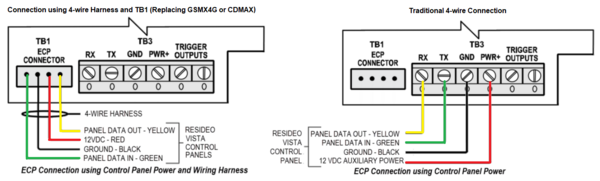
If using a 4-wire harness from an existing GSMX4G or CDMAX, then follow the wiring in the image on the left below. The wiring harness should only fit on the TB1 connector one way, but be sure the wire colors match what is shown below. If you don't have a 4-wire harness, then follow the wiring shown in the image on the right below. Be sure while making wiring connections, that the communicator and the panel are both powered completely down. By following the color scheme shown below, you can help to ensure that you make the proper connections on the panel side: -
Make connections at the panel. Once the connections have been made at the communicator, you're ready to connect the wires on the panel side. For this FAQ, we're assuming that you will be connecting to one of the VISTA alarm systems, so all of the information in this step will reflect one of those panels. There are basically two flavors of VISTA panel. There are the non-polling loop panels such as the VISTA-15P, VISTA-20P, and VISTA-21iP. And then there are the polling loop panels such as the VISTA-128BPT and VISTA-250BPT. We'll cover each of these in turn.
For the non-polling VISTA panels, the keypad bus terminals are terminals 4, 5, 6, and 7. If you maintained the color code described above, or if you're using the 4-wire harness, then this portion of the wiring should be pretty easy. Please note, depending on the wire manufacturer, 4-conductor wire may come in Black, Red, Green and Yellow or Black, Red, Green, and White. The Yellow and White conductors are interchangeable. The diagram will always show Yellow because it can't be shown in White.

For the VISTA panels that support a polling loop, the keypad bus terminals are 6, 7, 8, and 9. Refer to the diagram below to determine which wire color should be connected to which terminal. Again, if you maintain the suggested color code at the radio side, or if you are able to use a 4-wire harness, then this part should be relatively simple. The same information about the Yellow or White wire conductors being interchangeable also applies here.
Important Note: If you have wires going from the panel AC terminals (Panel Terminal 1 and Panel Terminal 2) to the communicator, be sure to remove those wires before powering the panel up. You will not be sharing AC Power in this wiring configuration.

-
Power up. Once the wiring connections have been made at the communicator and at the panel, you are ready to power up. Connect the AC transformer for the panel to the outlet. Use the locking screw to screw the transformer into the center of the outlet cover. This prevents the transformer from easily becoming disconnected. In some cases, without the screw, the transformer's own weight may pull it loose from the outlet. Reconnect the red lead to the panel battery. If you decide you want to connect the communicator's battery, now is the time to make those connections. There should be prepared battery cables with the LTEM-PA or LTEM-PV. Connect one end of black lead to the appropriate spade connector at the communicator and the other end to the appropriate connector on the included battery. Perform these same steps with the prepared red lead.
By connecting the communicator battery, you are allowing the communicator to run off of the panel's DC power output. If an AC loss condition occurs at the panel, both the panel and the communicator will run off of the panel's backup battery. If the AC outage lasts long enough, eventually the panel battery will run low, and if power is still not restored, then the panel will shut down to prevent damage to the panel battery (deep discharge). At this point, the communicator's backup battery will kick in, allowing the communicator to send a signal to the monitoring station letting them know that it has lost its connection with the alarm panel on the keypad bus.
Depending on the report codes that are enabled in the panel, in a situation like this the monitoring station would receive an AC Loss from the panel (E301) then a low battery from the panel some time later (E302) if the power outage continues. Then eventually a communicator power loss (E337) and a communicator ECP Supervision (E355) once the panel is completely powered down, but the radio still has its own battery power. The communicator will send its own low battery signal (E338, zone 803) if power remains out and will eventually shut down also. When AC power is restored, the panel will send an AC restore (R301), and eventually all other signals will restore with the communicator sending a power on reset (E339) when it begins receiving power again.
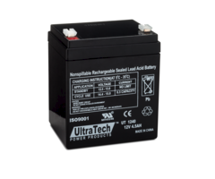
Connecting the communicator battery may result in a slightly higher load being placed on the panel battery during an AC loss condition, but it may be worthwhile in order to get all of the signals referenced above. Without the communicator battery being connected, once the panel reaches the point where it will power down completely, no further signals will be sent from the communicator, as it will power down at the same time. The user could slightly increase the panel's backup battery, for example, if you would normally have used a 4 Ah backup battery, choose to use a 7Ah battery instead, to allow for the slightly higher current requirement, and to be sure that the panel will still have 24 Hours of standby available in the event of an AC Loss.
Important Note: There will be no connection between the panel's AC terminals and the communicator (Panel Terminal 1 and Terminal 2). If your previous communicator had wires connecting the panel AC terminals to the communicator, please be sure to completely remove these wires before powering the panel back up.


Did you find this answer useful?
We offer alarm monitoring as low as $10 / month
Click Here to Learn MoreRelated Products


Related Videos

- Answered
- Answered By
- Julia Ross