How Do I Install a Resideo LTEM-PA or LTEM-PV to a Honeywell VISTA-20P?
The LTEM-PA or LTEM-PV connects to a panel's ECP bus. It uses a 3-wire harness (included) to connect to TB1 on the LTEM-Px. From the harness three (3) wires are connected to panel Terminal 4 (Black), Terminal 6 (Green), and Terminal 7 (Yellow). The communicator is powered by a DC Transformer.
The Resideo LTEM-PA and Resideo LTEM-PV (hereinafter referred to as LTEM-Px) are the latest communicators released by Resideo. They connect to the AT&T and Verizon LTE-CAT-M1 networks respectively. These communicators are meant to be supported far into the distant future. They have a modular design that allows a number of different plug-in modules to be added to the base communicator. For example, if the built-in LTE-CAT-M1 cellular module is not providing enough bandwidth, or doesn't have an adequate signal, then a Honeywell Home PROLTE-A or Honeywell Home PROLTE-V can be installed and used instead. Likewise, if there is no way to get a wired ethernet connection to the location of the communicator, then a Honeywell Home PROWIFIZW or Honeywell Home PROWIFI can be added in order to support a WIFI internet connection. For instructions on installing the WIFI module, check out this FAQ. Only one of these two paths, WIFI or Wired Ethernet can be used. In the future, when LTE is replaced by new technology, a new communicator module can be added, without disconnecting any wiring, or replacing the entire communicator. This makes it very DIY friendly.
Follow these steps to install a Resideo LTEM-Px communicator to a Honeywell VISTA-20P:
1. Remove old communicator. If you are replacing an older communicator, first power down the entire system. This involves unplugging the red lead from the panel battery and then disconnecting the transformer from the wall outlet. If you cannot find the transformer you can drop power at the circuit breaker instead. You should not attempt to remove the power wires at the panel as this could result in damage to the panel and/or the transformer.
Once the panel is powered down remove the existing communicator. This is important because there can be only one AlarmNet communicator connected to the ECP (Keypad) bus of a VISTA panel at any given time. If you are replacing a communicator from another manufacturer, then you'll likely want to remove it as well. Contact us at support@alarmgrid.com for more information if you find yourself in that situation. If there is an existing AlarmNet communicator it will be connected to the panel through terminals 4 - 7.
There are usually a number of different devices connected to these terminals so you'll need to isolate which ones are for the communicator. Then, loosen each of the screw terminals in turn to remove only the existing communicator's wiring, making sure to replace any wires that are connecting other devices to the panel. If you have a large number of wires connected and you are having trouble determining which ones belong to the old AlarmNet communicator, you may need to get a wire tracing tool like the Platinum Tools TP150. Once you've isolated the correct wires and removed them from the panel you're ready to begin installing the new LTEM-Px.
2. Determine Mounting Location. Whenever possible, the LTEM-Px should be mounted at the top of the VISTA-20P's metal enclosure. Doing so allows the use of the 3-wire harness that comes included with the unit. However, adequate signal strength is the most important factor in determining the proper mounting location. So before permanently mounting the device, power the unit on by connecting the DC power adapter and the battery to the LTEM-Px.
Open the unit by depressing the two tabs on the bottom edge of the communicator while pulling the front cover away from the back. This is a good time to make note of the communicator's MAC and CRC. If possible, take a picture of the stickers inside the communicator for later reference. Be sure to observe proper polarity at both the panel and the power adapter when connecting the power wires. This is a temporary connection, use only enough wire to get the power adapter connected to the panel.
The battery retention clip is installed from the factory, but the battery is not. For this reason, you'll need to remove the battery clip before you place the battery. Press in on the side of the battery tab closest to the center of the communicator. Once the tab clears the retaining slot, swing the clip open. Place the battery then return the battery retention clip to the previous position. You should not have to remove the battery again during this process unless it is too heavy to allow you to properly mount the unit. Connect the provided battery leads, making sure to observe proper polarity.
Important! Do not connect the battery terminals until AFTER the DC Power Adapter has been connected and plugged in.

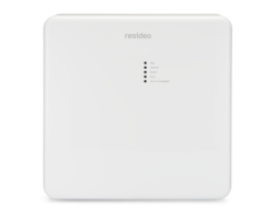
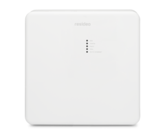
When the power adapter and battery have been connected, the unit will boot up and the LEDs that are normally visible through the front cover will blink in sequence repeatedly from top to bottom. The initialization sequence can take up to 15 minutes. It is important that the unit remain powered up during this entire process! When initialization is complete, the LEDs will begin to signify normal operation (see table below). After the first initialization, subsequent initializations due to reboots or network changes may take up to 90 seconds to complete.
The table below shows the LEDs and their functions once initialization is complete:
LTEM-Px LEDs And Their Function
| LED Color | LED Name | LED Function |
|---|---|---|
| Green | Registration | ON - Communicator is Unregistered OFF - Communicator is Registered FAST BLINK - Download session in progress |
| Yellow | Status | Steady Blink - Normal (Power ON) Fast Blink - Unable to Deliver Signals Slow Blink - Idle, Power Issue |
| Red | Fault | ON - No Contact With Network OFF - Normal Fast Blink - No Network AND Panel Connection Lost Slow Blink - Panel Connection Lost |
| Green | Cell | ON - Minimum Required Signal Received OFF - Cell Not Enabled Fast Blink - Poor Signal Quality |
| Green | WIFI* | ON - Connected to Internet via WIFI OFF - WIFI Not Enabled Fast Blink - WIFI Enabled, No Internet Connection |
| Green | Ethernet* | ON - Connected to Internet via Ethernet OFF - Ethernet not Enabled Fast Blink - Ethernet Enabled, No Internet Connection |
| *Only one technology, WIFI or Ethernet can be used. The bottom Green LED will indicate status for whichever technology is in use. | ||
Once initialization has completed, the DC Power Adapter can be unplugged to allow free movement within the premises. Place the radio in the area where you want it to be installed and check the signal strength. Be sure the Green Cell LED is on solid in the location where you intend to mount the radio before you proceed with installation. It is ideal if the radio can be mounted to the top of the alarm panel enclosure, however good, strong signal strength is more important than ease of installation. The best mounting location will be indoors, in a clean dry area away from things like ductwork, AC or intercom wiring, HVAC equipment, and wireless network equipment. The best areas for good signal strength are usually higher within the building. Attempting to install in a basement is not advisable. Once you have determined where you will mount the communicator you're ready to perform the install.
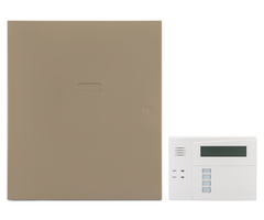
3. Install the communicator. With the front and the back of the LTEM-Px still separated, locate the back of the unit in the area where you plan to perform the install. If you plan to install the communicator at the top of the alarm panel enclosure then you will need to first remove the round knockout from the upper LEFT side of the cabinet. You can remove this with a hammer, or the handle of a screwdriver.
This image shows a knockout on the upper RIGHT side of a panel's metal enclosure. There is another one just like this on the LEFT side. Be sure to choose the one on the LEFT:

For those installations to the top of the VISTA-20P, the communicator comes with a threaded bushing. Inside the communicator, in the lower left, you'll see a plastic knockout that you need to remove. The threaded bushing will slide into the hole created by this knockout and snap into place with plastic retaining tabs. The plastic threads will then be sticking out through the bottom. The threaded bushing will fit into the knockout at the top left of the panel's metal enclosure. A silver locking nut is also included with the communicator. Once the threaded bushing has been passed through the hole at the top left of the enclosure, lock it in place using this nut. The wires for power and the ECP connection will pass through the space within threaded bushing and into the panel enclosure.
LTEM-Px mounted to VISTA panel cabinet. Wiring routed through the threaded bushing to the panel:

Please Note: Once the installation is complete, when the front cover for the communicator is put back on, it may be difficult to remove it again because the bottom of the communicator is right against the top of the panel. This blocks access to the retaining tabs at the bottom of the LTEM-Px. For this reason, be sure you are done with the inside of the communicator before you put the cover on. It can be removed again, but it takes a little patience.
If signal strength at the alarm panel is not adequate for the LTEM-Px then you will need to install it in a more suitable location. In that case, you may decide to run the wiring through the wall at the back of the communicator and fish it from there to the panel. With that in mind, the first task is to create a wiring hole, then run wires from the alarm panel to the communicator mounting location and through the hole you've created for this purpose. The hole only needs to be large enough for the wires to pass through. It doesn't really matter if you start at the panel and move toward the communicator, or if you start at the communicator and move toward the panel. It's usually easier to begin at whichever device is higher. Gravity will work in your favor if you do. There are a few knockouts available on the backplate of the communicator that can be used to route wires while allowing the backplate to mount flush to the wall. If you don't feel comfortable fishing wire, or if it isn't possible to do so, this is an alternative.
There are a total of five (5) wires for this device. Three (3) are for the Panel Data-in (Radio - TX), Panel Data-out (Radio - RX), and Panel Common (Radio - GND) and two (2) are for power. It is not a requirement that the power wires be run all the way back to the alarm panel. The DC transformer can be installed at any outlet that's not controlled by a wall switch. There are limits for power wiring, based on length and wire gauge. Choose where you will install the DC power adapter based on this information. The chart below shows these wire limits:
DC Power Supply Maximum Wire Lengths
| Maximum Distance From Adapter to Communicator | Wire Gauge (AWG) |
|---|---|
| Up to 25' (7.62m) | #22 |
| Up to 45' (13.72m) | #20 |
| Up to 70' (21.34m) | #18 |
| Up to 110' (33.53m) | #16 |
It is possible to wire the communicator to receive its DC power from the alarm panel, rather than from the DC Power Adapter. If you need to use this wiring configuration as opposed to using the power adapter that came with the communicator, please refer to this FAQ.
The wire run limits for the other three (3) wires are the same as those for any device that is connected to the ECP (Keypad) bus. See the chart below for the limits on the ECP bus wire.
ECP Bus Connection Maximum Wire Lengths
| Maximum Distance From Control Panel | Minimum Wire Gauge (AWG) |
|---|---|
| Up to 75' (23m) | #22 |
| Up to 120' (37m) | #20 |
| Up to 170' (52m) | #18 |
| Up to 270' (82m) | #16 |
All the wiring information contained in this FAQ refers to unshielded wire.
The backplate will affix to the wall using six (6) of the included mounting screws. There should be three (3) screws along the top of the communicator, and another three (3) along the bottom. The seventh (7th) screw is meant to secure the Wall Tamper in the rear of the communicator to the wall. The wall tamper cannot be used with the communicator when it is mounted atop the VISTA-20P metal enclosure.
4. Complete the wiring. Once the LTEM-Px is locked in place either at the top of the panel or mounted to the wall you can complete the wiring connections. There are two (2) options for wiring. Using the included 3-wire harness, or running custom-length wire yourself. We'll cover both options below:
3-Wire Harness Wiring Connections
The 3-wire harness included with the LTEM-Px will connect to the LTEM-Px at the TB1 ECP Connector. This is a port located directly to the left of the terminal block. See the image above showing the threaded bushing with the wiring routed through it. Once the wiring is routed, make the following connections:
- Green -> Panel Terminal 6 (Data In)
- Black -> Panel Terminal 4 (Aux Power Negative)
- Yellow -> Panel Terminal 7 (Data Out)
This image shows the wiring connections at the communicator:

In addition to the ECP connections, you will need to make a permanent connection between the panel and the transformer. Transformer wiring can be routed down through the threaded bushing, and then out through one of the knockouts in the VISTA-20P panel. Otherwise, it can be routed through one of the plastic knockouts around the edge of the LTEM-Px mounting plate. Be absolutely certain that you observe proper polarity. Reversing polarity will likely damage both the communicator and the transformer.
It is possible to wire the communicator to receive its DC power from the alarm panel, rather than from the DC Power Adapter. If you need to use this wiring configuration as opposed to using the power adapter that came with the communicator, please refer to this FAQ.
Custom-Length Wiring Connections
If the communicator will be too far away from the panel to allow the use of the provided harness, you'll need to cut wire to fit your needs. Be sure to observe the wire run limits based on length and gauge as noted in the tables above. If you don't already have a box of wire, and you need a relatively short wire run, Alarm Grid offers pre-cut 10-foot, 15-foot, and 25-foot sections of 22AWG/4-Conductor wire at a reasonable price.
The 3-wire harness wire will be pre-stripped. With custom-length sections, you'll need to strip the color coating off at either end of the wire. If you don't have wire strippers you can use a pair of sharp scissors. Close the scissors on the wire until they just barely bite into the coating, then spin them around a few times to make a groove all the way around the wire, making sure not to cut too deep. Once you have a groove all the way around you should be able to peel off the section at the end. You'll want to remove about 1/8" to 1/4" of the color coating at either wire end.
By the time you've reached this point, you should have decided whether you will be fishing your wire, or using one of the plastic knockouts on the communicator to surface-run your wire. Once the wire has been run between the two, and the ends have been stripped, make the following wire connections at the communicator and the panel:
- Communicator-RX-Yellow -> Panel Terminal 7 (Data Out)
- Communicator-TX-Green -> Panel Terminal 6 (Data In)
- Communicator-GND-Black -> Panel Terminal 4 (Aux Power Negative)

Be sure to connect the DC Power Adapter, observing proper polarity. If you reverse polarity at either end, damage to the communicator and/or the power adapter may occur. Observe the wire length and gauge guidelines shown in the table above. Power wiring and ECP wiring do not have to be routed together. It is always best to keep power wire runs as short as possible, so choose an un-switched outlet that's close to the mounting location for the communicator, not necessarily close to the alarm panel.
We've had some difficulty with activation on these communicators since their release. Based on our experience, it is recommended, once the communicator has been powered up for the final time, to default the communicator. You never know what kind of Quality Assurance testing may have occurred at the factory. A default will clear out any leftover programming and set the unit back to factory settings. To default, hold down the red button located in the upper right of the main communicator board for at least 20 seconds, then release it. You should see the LEDs on the communicator go through their power-on sequence and then settle back to normal. Once this occurs, perform a full power cycle. Do this by unplugging the transformer, and unplugging the battery. Wait thirty seconds, then plug in the battery, then the transformer.
5. Close the communicator. Once all wiring has been completed, replace the cover on the communicator. Put the top in place first making sure to line it up with the two hooked tabs at the top. Once the top is properly aligned, swing the bottom down and snap it into place over the bottom locking tabs.
6. Activate the communicator. Using the information you gathered when you opened the communicator to check signal strength, provide the MAC and CRC to your alarm dealer and they will assist with getting your LTEM-Px activated.
Did you find this answer useful?
We offer alarm monitoring as low as $10 / month
Click Here to Learn MoreRelated Products


Related Categories
- Small Business Security Systems
- Monitored Home Security Systems
- 1000-Feet 18/2 Alarm Wire
- 1000-Feet 18/2 Alarm Wire
- DIY Wired Security Systems
- Answered
- Answered By
- Julia Ross