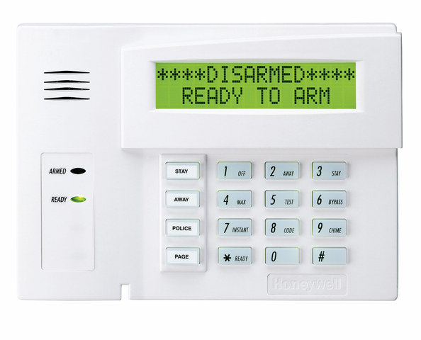
How Do I Add a Second Push-Button Keypad to a VISTA 20P?
You can add a second push-button keypad to a VISTA 20P by wiring it to the panel and assigning it to a proper address. Panel terminals 4 through 7 are used for keypads. Push-button keypads like the 6160 and 6150 use addresses 16 through 23. Address 16 is usually for the first system keypad.
Please note that the steps presented below only apply to push-button keypads. If you want to add a touchscreen keypad like a Honeywell Tuxedo Touch or a Honeywell 6280, you should review this FAQ, which outlines both keypad types. Complete the following steps to add a push-button keypad to a VISTA 20P System:
1. Power down the system. You cannot add a keypad to the system while it is powered on. Doing so may result in damage to the system or the keypad. Fortunately, it is very easy to power down a VISTA System. First disconnect the wires from the backup battery. Then unplug the AC transformer. Any keypads currently set up with the system should go blank, and any system LED lights should shut off. This serves as indication that the system is now powered off. Keep in mind though that any keypad using an auxiliary power supply instead of panel power will remain powered on. These keypads will display an error of "Open CKT", "OC", or "ECP Error".
2. Connect the keypad. A push-button keypad will connect to a VISTA 20P using a 4-wire connection. Two wires are for power (usually red and black), and two wires are for data (usually green and yellow or white). We recommend using an 18-gauge, 4-conductor wire for this process.
If you are using standard colored wire, then the following connections will be made:
- Black wire at negative power [-] at the keypad and terminal 4 at the panel.
- Red wire at positive power [+] at the keypad and terminal 5 at the panel.
- Green wire at data-in [G] at the keypad and terminal 6 at the panel.
- Yellow or white wire at data-out [Y] at the keypad and terminal 7 at the panel.
Please note that if you intend to use an auxiliary power supply with the keypad, then the black wire should instead go to DC negative [-] at the power supply. The red wire should go to DC positive [+] at the power supply. Any time you use a separate power supply for anything connected to the keypad bus, you must have a common ground between the power supply and the VISTA panel. This means be sure to connect a wire from DC negative (-) on the power supply to terminal 4 on the alarm panel.
You can see the panel terminals in the following diagram:

3. Address the keypad. Push-button keypads can use addresses 16 through 23. In most cases, address 16 is used with the first keypad. You will probably be using a different address for an additional keypad. It doesn't really matter which address you use, as long as each keypad has a different address. However, you should make sure to remember which address you use in case you go to add more keypads later on.
Start by powering the system back on. You can do this by plugging the transformer back in. You can then reconnect the backup battery. You can now verify that your new keypad was wired correctly, as it should power on. Go to the new keypad, and press and hold the [1] and [3] keys. You must do this within 60 seconds of powering the system on. The current set address should be displayed. This is address [31] by default. First enter [00] to clear the current address. Then enter the 2-digit address you want to use. The easiest thing to do is use [17] for your second keypad, [18] for your third keypad, and so on. Remember, you only have eight (8) addresses available, so you cannot use more than eight (8) push-button keypads with your VISTA 20P System.
4. Enable the address. You now need to enable the address for the keypad you're adding. You must do this at your system's primary keypad, as the address for your new keypad has not yet been enabled. Please note that VISTA 20P Panels running Firmware Revision 10.23 and higher have keypad addresses 16 through 23 enabled by default. If your 20P is Version 10.23 or higher, then you can skip this step.
Please Note: If you only have a single keypad on your system, and you intend to replace that single keypad with another keypad, then you would be better served by this FAQ.
If you need to enable a keypad address, you will have to enter programming. This is done with the command [Installer Code] + [800]. Remember that the default Installer Code is 4112. Once in programming, enter the [*] plus the programming field you want to use. [*190] is used to enable address 17, [*191] to enable address 18, and so on. The final keypad address slot, address 23, is [*196].
After entering the appropriate [*] field, you will first need to set the partition for the address. [0] will disable the associated keypad address. [1] will set the associated keypad address to partition 1. [2] will set the associated keypad address to partition 2. And [3] will set the associated keypad address to partition 3, which is the common-lobby partition.
After making your partition selection, you will move on to making the sound selection. [0] will have all sounds enabled for this keypad address. [1] will suppress arm/disarm beeps and Entry/Exit beeps. [2] will suppress chime beeps. [3] will suppress arm/disarm beeps, Entry/Exit beeps, and chime beeps. After the second digit entry, the keypad will emit three beeps to acknowledge that you have filled the programming field. If you want to verify your entries, press [#], plus the programming field number. The keypad will read back Partition # entry - beep - Sound Option entry - beep-beep-beep.
After doing this, you can now enter [*99] to exit programming. Never use any other command to exit programming.
5. Test the keypad. Try using your new keypad to arm the system. You can do this by entering the command [Master Code] + [2] at your new keypad. Make sure the system arms. Then try to disarm at the same keypad by entering [Master Code] + [1]. The system should then disarm.
If you find that the new keypad isn't working properly, you can try rebooting the system and then trying the arm/disarm process again. You might also try checking your address settings. Make sure that you don't have multiple keypads at the same address. Lastly, you can check the wiring to make sure the keypad is wired correctly.
Did you find this answer useful?
We offer alarm monitoring as low as $10 / month
Click Here to Learn MoreRelated Products


Related Videos

Related Categories
- Answered