Intro to the 2GIG GC2
The 2GIG Go!Control, also referred to as the GC2, is an incredibly versatile security panel with many uses and capabilities. But as an alarm system, its main function consists of interacting with a variety of different sensors. Each sensor is programmed with the GC2 System individually. The system can readily interface with a large number of wireless sensors as needed. However, the sensor programming process for the GC2 System is a little different from most other wireless security panels. This guide will help you with every step necessary to get sensors up and running with a 2GIG GC2 Alarm System.
The Panel - Basic Information
Before attempting to program a 2GIG GC2 Panel, it is helpful to know a little bit about the system. The GC2 is an all-in-one alarm system with a built-in 3.75" by 2.25" touchscreen controller. This makes it easy for the user to navigate between menus and make programming adjustments. The panel includes an integrated wireless receiver, allowing any sensor with a wireless frequency of 345 MHz to interface with the system. This is famously the same wireless frequency used by Honeywell 5800 Series Sensors. This means that any Honeywell 5800 Series Sensor and any 2GIG Sensor can communicate with the system. Finally, the GC2 Panel provides 60 different wireless zones for setting up wireless sensors with the system. It also includes two built-in hardwired zones and a Z-Wave controller for smart home devices.

Accessing System Configuration - Zone Programming
In order to set up any wireless sensor with a GC2 System, the user must access the System Configuration Menu. The System Configuration Menu is also sometimes referred to as Zone Programming. This menu serves as the primary hub for learning-in new sensors. Accessing this menu is key for setting up a GC2 Panel.
To access System Configuration, start from the home screen of the GC2 System. Press the Go!Control icon in the bottom-right corner of the screen. Then enter the Installer Code for the system. The default Installer Code for a GC2 Panel is 1561. We recommend keeping the Installer Code at the default so that you do not become locked out of programming later. After entering in the Installer Code, choose the option "System Configuration". This will take you to the System Configuration Menu.
Navigating System Configuration - Selections, Questions and Sub-Questions
The System Configuration screen (shown in the picture below) consists of a numerical keypad, four arrows, and buttons labeled "go to", "skip", "sum", "esc" and "end". Depending upon the current selection, different buttons may be available. The system uses question-based programming that may seem a little confusing to new users. But once you know how to navigate this menu, the process becomes more intuitive. A good way to think about this is that each "Question" represents a different menu option for the GC2 System
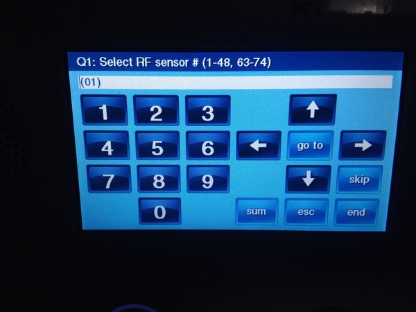
When navigating the System Configuration menu, you should always pay attention to the "Question" at the top of the screen. This is indicated by the letter Q, followed by a number, and then the current menu option (Question). Checking this information will let you know what setting you are currently configuring. For example, the first Question is as follows:
Q1: Select RF Sensor # (1-48, 63-74)
For this Question, you are choosing the wireless zone that is being configured. A zone can be assigned a wireless zone numbered 1 through 48, or 63 through 74. The white rectangular box below the Question shows the current selection.
Pressing the right and left arrows will allow you to navigate between different possible selections for that Question. For example, let's say that you are on Q1: Select RF Sensor # (1-48, 63-74), with a current selection of (02). Pressing the right arrow will take you to the next possible selection of (03). Pressing the left arrow will take you to the previous possible selection of (01). Keep scrolling through the possible selections until you reach the one needed. You will stay within the same question while doing this.
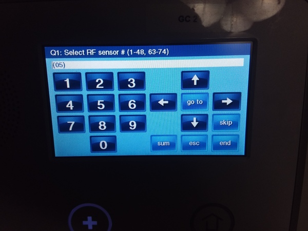
Alternatively, you can also use the numerical keypad on the left to put in the digits associated with the desired selection. For example, if you are on Q1: Select RF Sensor # (1-48, 63-74), entering in "05" will automatically adjust the current selection to (05). This can be a quick way to make a selection, without having to manually scroll between different options. Again, you will stay within the same question.
Within Questions numbered 1 through 4 on the GC2 System, there are various Sub-Questions. These Sub-Questions are used to provide additional options for the menu selection that is being programmed. Pressing the up and down arrows will take you to a different Sub-Question for the current setting that is being configured. A Sub-Question can be identified by having no number following the letter Q. Pressing the down arrow will take you to the next Sub-Question. Pressing the up arrow will take you to the previous Sub-Question within the sequence.
Please note that in some cases, pressing the up or down arrows will simply take you to the next Question in the sequence, rather than a Sub-Question. That is why it is always important to keep a close eye on the current Question at the top of the screen when programming a GC2 System. Remember, you will only have to consider Sub-Questions for Questions 1 through 4 on the system.
There also other ways to navigate between Questions. Pressing the "skip" button will automatically take you to the next Question in the sequence. For example, if you are on Q4, pressing the "skip" button will take you to Q5. Please note that the "skip" button will no longer be available for Q5 onward. At this point, pressing the down arrow will take you to the next Question in sequence. The "skip" button is removed for Question 5 onward due to the fact that these Questions have no available Sub-Questions. Instead, pressing the down arrow accomplishes the same goal.
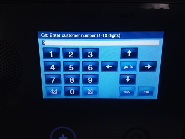
You can also press the "go to" button to manually enter a 2-digit Question number and be taken to that Question. A single-digit Question number will be entered with a 0 in front of it - e.g. 07 for Q7. Please note that there are a total of 97 possible Questions on a 2GIG GC2 System. Entering in a 2-digit Question number higher than 97 (98 or 99) will take you to Q97. There is also a Q0 on the system for Question 0.
Using Question 1 to Learn-In Wireless Sensors
With 97 different Questions available on a GC2 System and various Sub-Questions available as well, programming a GC2 System can certainly seem intimidating at first glance. But fortunately, the vast majority of sensor programming is accomplished through Question 1 and its set of Sub-Questions. This makes learning-in a new sensor with the system a relatively easy process. To thoroughly explain the process, we will go through Question 1 and its Sub-Questions in their entirety.
As explained in the previous section, the main selection of Question 1 involves choosing RF Sensor Number, also called the Zone Number. A Sensor Number of 1 through 48 or 63 through 74 can be selected, for a total of 60 possible wireless sensors. Enter in the 2-digit Sensor Number to choose which Zone Number you will be working with. Once you have made the selection, you can press the down arrow to move on to the first Sub-Question of Question 1.
Setting the Sensor Type
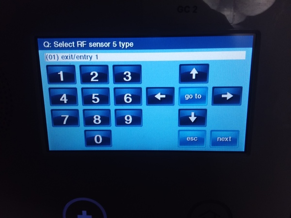
The first Sub-Question is the Sensor Type, which might also be called the Response Type. There are many options available. You can scroll between different options by pressing the right and left arrows. We will now go through each and every one:
(00) Unused - This means that no sensor is being used for that Sensor Number. In other words, this wireless zone is open.
(01) Exit/Entry 1 - If the sensor is activated while the system is armed stay or armed away, then the system must then be disarmed within the system's entry delay 1 period (set in Question 6 of programming). If the system is not disarmed within this time period, an alarm will occur.
(02) Exit/Entry 2 - If the sensor is activated while the system is armed stay or armed away, then the system must then be disarmed within the system's entry delay 2 period (set in Question 7 of programming). If the system is not disarmed within this time period, an alarm will occur.
(03) Perimeter - If the sensor is activated while the system is armed stay or armed away, an instant alarm will occur.
(04) Interior Follower - If the sensor is activated while the system is armed away, an instant alarm will occur, unless an Entry/Exit zone was activated first. If the system is set to armed stay, then the sensor will be bypassed and unable to cause an alarm.
(05) Day Zone - If the sensor is activated while the system is armed stay or armed away, an instant alarm will occur. Additionally, if the sensor is activated while the system is disarmed, a trouble condition will occur.
(06) 24-Hour Silent Alarm - If the sensor is activated, an instant alarm will occur. However, no siren or strobe will occur on the system. This will always occur, regardless of whether the system is armed or disarmed.
(07) 24-Hour Audible Alarm - If the sensor is activated, an instant alarm will occur. Any siren that has been set up with the system will activate. This will always occur, regardless of whether the system is armed or disarmed.
(08) 24-Hour Auxiliary Alarm - If the sensor is activated, the system sounder will activate, and an instant alarm will occur. However, any external siren or strobe programmed with the system will not activate. This will always occur, regardless of whether the system is armed or disarmed.
(09) 24-Hour Fire - If the sensor is activated, an instant alarm will occur. Any siren that has been set up with the system will activate. This will always occur, regardless of whether the system is armed or disarmed.
(10) Interior with Delay - If the sensor is activated while the system is armed away, then the system must be disarmed within the system's entry delay 1 period (set in Question 6 of programming). If the system is not disarmed within this time period, an alarm will occur. If the system is armed stay, then the sensor will be bypassed and unable to cause an alarm.
(14) 24-Hour Carbon Monoxide - If the sensor is activated, an instant alarm will occur. Any siren that has been set up with the system will activate. This will always occur, regardless of whether the system is armed or disarmed.
(16) 24-Hour Fire with Verification - If the sensor is activated twice within a two minute period, or if the sensor is activated and remains activated for 30 straight seconds, an instant alarm will occur. Any siren that has been set up with the system will activate. This will always occur, regardless of whether the system is armed or disarmed.
(23) No Response Type - The sensor will not be able to cause any system events, including alarm conditions. However, the sensor can still be monitored by a central station, and activity alerts can still be sent to Alarm.com.
(24) Silent Burglary - If the sensor is activated while the system is armed stay or armed away, a silent alarm will occur. A distress signal will be sent out to a central station. However, the system sounder, along with any sirens or strobes, will not activate.
Upon setting the Sensor Type, you can press the down arrow to move on to the next Sub-Question.
Setting the Equipment Type
The options available for the next Sub-Question of Q1 will depend upon the Sensor Type that was selected in the previous Sub-Question. In some cases, you will be prompted to choose a specific equipment code. You can use the right and left arrows to scroll through the possible selections.
For other Sensor Types, you may be asked to select a generic equipment type, such as a contact or a motion. The selections available will depend on the Sensor Type that was chosen.
Once you have made the appropriate section, press the down arrow to move on to the next Sub-Question.
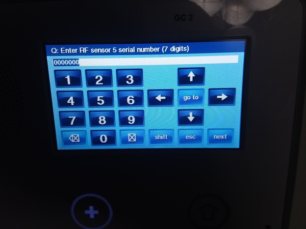
Setting the Serial Number
The serial number is a 7-digit code that is unique to each individual sensor. The serial number is usually located somewhere on the sensor, and it can be manually entered into the system. However, we strongly recommend auto-enrolling any sensor to have the serial number learned-in automatically. Not only will this prevent you from mis-entering the serial number, it will also ensure that the sensor is able to communicate properly with the GC2 System.
To auto-enroll the sensor, first press the "shift" key. Then press the "learn" key that will appear on the left side of the screen. You will be taken to a screen titled "Activate a sensor to learn its ID", along with the message "Waiting for RF sensor # transmission...". From this screen, activate the sensor you want to learn-in.
The process for activating the sensor will depend on the type of sensor that is being used. For example, a door and window contact will require you to separate the sensor from its magnet, while a smoke detector will have you activate the device's tamper switch.
Once the sensor has been detected, its Type and ID Number will be displayed on the screen. Verify that the information is correct, and press the OK button in the bottom-right corner of the screen. Then press the down arrow to move on to the next Sub-Question.
Continue Programming the Sensor
As you continue to move through the various Sub-Questions, you be able to apply various programming settings for the sensor.
Equipment Age has no affect on the performance of the sensor. The idea is that you can choose 0 if the sensor is brand-new, and 1 if the sensor was used previously. Either selection will work just fine.
The Loop Number is important for ensuring that the sensor performs as it should. Many sensors can perform multiple functions by setting a different Loop Number for the device. Check the manual for the sensor to determine which Loop Number should be used.
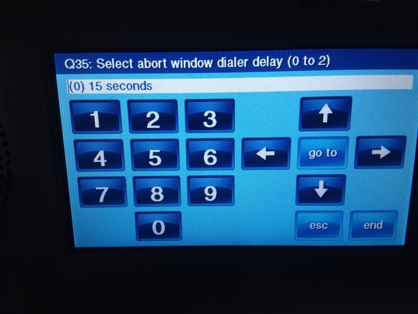
The Dialer Delay option determines whether or not dialer delay will be enabled for the sensor. This feature instructs the sensor to delay the process of sending out a notification signal to the user or a central station. Setting this option to 0 will have Dialer Delay disabled, while setting it to 1 will have the feature enabled. A user can set the Dialer Delay for their GC2 Panel by going to Question 35 of System Configuration. Selections of 15 seconds, 30 seconds and 45 seconds are available.
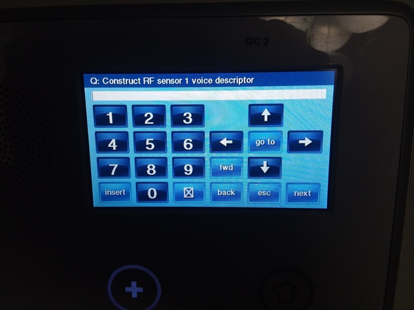
Setting the Voice Descriptor
The Voice Descriptor is the audio annunciation the system will use to verbally identify the sensor. The GC2 Panel includes a built-in voice function that it uses to read out the Voice Descriptor for any given sensor. The Voice Descriptor for a sensor is determined by choosing a set of preprogrammed words for the panel to read out. Up to five individual words can be applied to a single Voice Descriptor. Because of the amount of options available setting the Voice Descriptor can seem challenging at first. But the process is actually very simple.
To add a new word to the Voice Descriptor, press the "insert" button. With a word highlighted, you can the choose the desired word in one of two ways. You can either use the left and right arrows to scroll through the list of available words. Or you can also enter in the 3-digit code for any given word to have that word applied. Once you have entered the 3-digit code, the new word will automatically replace the highlighted one. The entire list of available words and their respective 3-digit codes is available on pages 38 and 39 of the 2GIG GC2 Programming Guide.
Remember, any additional words that you plan on including for the Voice Descriptor must be added by pressing the "Insert" button. To scroll between words, press the "fwd" button to move to the right, and press the "back" button to move to the left. To delete a word, highlight the word you want to delete, and press the picture of the box with an X in it.
Once you have finished setting the Voice Descriptor, press the down arrow to move on to the next Sub-Question in the sequence.
Setting the Final Sensor Options
The Sensor Reports option will determine whether or not the sensor will send out a report to a central station in the event that it causes an alarm. Set Sensors Reports to 0 for disabled and 1 for enabled. If you want the sensor to send a signal to a central station, this option should be set to 1 for enabled.
The Sensor Supervised option determines whether or not the GC2 System will periodically look for check-in signals from the sensor. If the Sensor Supervised option is enabled, the system will experience a trouble condition if the sensor is ever unable to communicate with panel. This could be caused by the sensor being taken out of range of the panel or by a dead battery on the sensor. However, even if Sensor Supervised is disabled, the GC2 System will still alert the user about a low sensor battery and for an activated tamper cover.
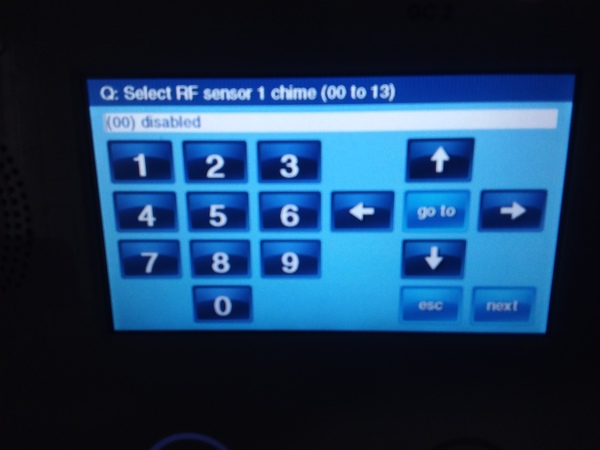
The Chime option is used to set an audible alert that will emit from the system whenever the sensor is activated. The Chime will play whenever the sensor is activated, even if no alarm is set to occur. You can use the right and left arrows to scroll between different Chime options. Any Chime with voice will have the Voice Descriptor spoken when the sensor is activated.
Finish Programming the Sensor
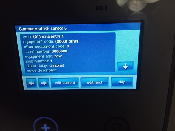
After pressing the down arrow from the Chime setting, you will be taken to a summary screen where you can view all of the selections you made for the configurations for that sensor.
Use the up and down arrows on the right side of the screen to view all of the selections. Use the left and right arrows in the bottom-left corner of the screen to scroll between the summary screens for different RF Sensors on the GC2 System (1-48 and 63-74).
Press the "edit current" button to make changes to the RF Sensor that is currently selected. Press the "edit next" button to make changes to the next RF Sensor in the numerical sequence.
Press "skip" to continue on to Q2: Select Wired Sensor # (1 to 2), which is used for programming the two hardwired zones that can be set up with the GC2 Panel.
Save Your Changes
If you are finished programming, press either of the "edit" buttons or the "skip" button. Then press the "end" button in the bottom-right corner of the screen. You will be taken to a summary screen that shows all of the current settings for Questions 5-97 in System Configuration. You can use the up and down arrows on the right side of the screen to review these settings. Pressing the "back" button in the bottom-left corner of the summary screen will have the system return to the System Configuration Menu so that you can make any additional changes that are necessary.
To finish and save your changes, make sure that the box next to "save changes" is checked. If it isn't, click on the box to apply a yellow checkmark next to the "save changes" setting. Then press the "exit" button in the bottom-right corner of the screen. The GC2 System will automatically reboot. Upon reloading, all of the changes that were made in the System Configuration Menu will be automatically applied and taken into effect.


