February 2021 Archives

Posted By

We have some exciting news from Alarm.com. The latest version of the Alarm.com Mobile App for iOS (Version 4.18) will make your enrolled smart locks compatible with Siri Shortcuts. This means that you will be able to control your smart locks with spoken voice commands. How convenient!


If you aren't familiar with Alarm.com Siri Shortcuts, they represent an innovative way to control your system and its integrated accessories using spoken voice commands. Each command is customized so that it performs the exact actions you want. Siri Shortcuts are available for iOS 12 and higher, so make sure your iOS device is on a high enough version before trying to set them up. We very strongly recommend reading this post from a couple years prior to refresh your memory on Siri Shortcuts and how they can be used. Overall, we think the Siri Shortcuts feature serves as a nice alternative to Apple HomeKit, which isn't compatible with Alarm.com or its associated security systems.

From what we can tell, the only way that a Siri Shortcut could control a smart door lock prior to Alarm.com iOS Version 4.18 was to do so indirectly through a smart scene. In other words, the user must create a smart scene that tells a door lock to LOCK or UNLOCK, and then create a customized Siri Shortcut to run that smart scene. Of course, a user would need separate scenes for LOCKING and ULOCKING, and they would need different scenes for each individual lock if they wanted complete control over their entire network of door locks. But with the update in iOS Version 4.18, smart lock control is made much more convenient and more easily accessible.

Thanks to the update, users can now create Siri Shortcuts that deal with locks directly, rather than being part of a smart scene. Each Siri Shortcut can control a single door lock, or a user can control all their locks at the same time with one single command. For a single lock, it's as simple as asking Siri to LOCK or UNLOCK a door based on the name of the lock. For example, you might say,

  • "Hey Siri, UNLOCK the FRONT DOOR."
  • "Hey Siri, LOCK the BACK DOOR."

Or if you wanted to control multiple doors,

  • "Hey Siri, LOCK all the doors."
  • "Hey Siri, UNLOCK every door."

Keep in mind that this door lock control for Siri Shortcuts is being made available in Alarm.com iOS Version 4.18. This update isn't available quite yet, but we expect it to be released in the coming days. At the time of this writing, the newest iOS Version we see is 4.17.3. You can check the version you're running by logging into the Alarm.com iOS App, and then choosing the Menu button (three horizontal bars) in the upper-left corner, and then selecting About in the bottom-left, and then About Alarm.com. The App Version will be displayed in white text across the top orange bar.


Remember to check the Apple App Store for the release of Alarm.com iOS App Version 4.18. Then open Settings within the Alarm.com Mobile App to access Siri Shortcuts. That is where you can enable the "Share Activity with Siri" settings and build customized Siri Shortcuts for use with your door locks. Remember that you can only control door locks that are enrolled with your Alarm.com account. Z-Wave door locks work great for this, and we have plenty of options available for purchase on our site if you are looking to get started.

Remember to check out our monitoring page if you are interested in starting monitoring service for access to Alarm.com. And please don't hesitate to reach out to us if you need help getting started with Alarm.com Siri Shortcuts for door locks. We're here to help you get the most out of your door locks and your Alarm.com service.

Tags: , , , , , , , , , , , , ,

Comments


Posted By

If you have a hardwired security system with wired sensors, then it's likely you have set up some End Of Line Resistors (EOLRs) with your equipment. Today, we're taking a quick look at these pieces of equipment to explain how they get their name and why they're important for your system.


The simplest way to understand resistors (end of line or otherwise) is that they reduce the flow of electrical current. These devices have many potential uses, but today we will be focusing on how they are used with wired alarm systems to supervise connected sensors. Basically, the presence of an End Of Line Resistor tells a system that no sensors have been tampered with on a zone.

On a wired alarm system, you may have many hardwired zones. If you look at a single wired zone, there can be multiple sensors of the same or similar type connected to it, all in a line. From the alarm panel input moving outward, you will find the first sensor in the line, then the second sensor, and so on, until you reach the final sensor. That sensor is the end of the line. At that last sensor, you will have the end of line resistor (EOLR).

The reason why you have the resistor at the end of the line is because cutting any of the sensors leading up to the last sensor will cause the system to lose track of the EOLR. Basically, by putting the resistor at the very end, the system knows that all the sensors leading up to it are still in-place. The entire line, the entire series, if you will, has its current slowed, or resisted, by the EOLR. Once you either remove any of the connected sensors or attempt to short out any of them, current will then stop flowing through the circuit. The system will detect this and know that, at somewhere in the circuit, something has been tampered with, and the user needs to be informed.

Remember, this is also how the zone works normally. In a circuit where the sensors are normally closed and the EOLR is wired in series at the end of the line, opening a sensor, such as when you open a door, also prevents the system from seeing the resistor, which is what causes the zone to display a fault condition. In most cases, burglary zones will only show a fault when a zone has been tampered with. Rarely will they cause a trouble condition, though in some cases, it is possible to configure a zone especially for this type of behavior.

In many cases, resistors are actually installed at the terminals on the panel. The reason this is a bad idea is that when the resistor is at the panel, a burglar could put a short across any point in a normally closed zone, and the only way the user would be able to detect it would be if they noticed that a particular point on the zone was open, a window for example, and should have been showing a fault, but that no fault was actually being displayed on the keypad. If this happened on your system, would you take notice right away? Granted, this assumes the burglar had access to the system while it was disarmed, and was able to set this up in advance.

The above scenario would imply that the protected premise is a business or a home with a good deal of service personnel coming in and out. We use this scenario just to illustrate why proper resistor placement is so important. This same vulnerability exists on hardwired zones that are programmed as normally closed, or normally open. Though with a normally open zone, the intruder would cut the circuit anywhere between the panel and the first sensor, rather than shorting it.

It should be noted that an EOLR will be wired according to the behavior of the zone type. That is, an EOLR will be wired in Series (in line) for a Normally Closed (NC) zone, or it will be wired in Parallel (across) for a Normally Open (NO) zone. Keep that in mind when configuring the EOLRs for the different zones on your alarm system. And if you have a zone without any connected sensors, then you can still have a resistor at the end of the line, but that "end of line" would just be across the zone terminals themselves. This is a good practice in order to keep up with any unused resistors, in the event that you want to add a supervised wired zone to the system at a later time.

We hope that this quick lesson in end of line resistors may be helpful to anyone who is new with alarms, and perhaps working with a wired alarm system or wired sensors for the first time. If you have any questions about setting up a wired security system, or if you are hoping to learn more about Alarm Grid monitoring services, please send an email to support@alarmgrid.com. We're here to check your emails from 9am to 8pm ET M-F. We look forward to hearing from you!

Tags:

Comments


Posted By

One product that we have yet to discuss in great detail is the Honeywell Home PROINDMV Indoor Motion Viewer. This is a very promising accessory for PROA7PLUS users, especially those who are looking for a more affordable alternative to Honeywell IP Cameras and true video surveillance service.


If you are familiar with image sensors, then the Honeywell PROINDMV Indoor Motion Viewer is exactly that, plus a bit more. It is part of the Honeywell Home PROSIX Lineup of wireless sensors, so perhaps PROSIXINDMV would have been a more appropriate name. But nomenclature aside, this is a very handy and useful sensor for anyone with a PROA7PLUS Alarm System, especially if your monitoring plan doesn’t include video surveillance, and you are looking to keep your monitoring costs down.

You can think of the PROINDMV as a PIR motion detection sensor, combined with a video camera. It should basically be treated as an interior motion. If its PIR sensor is triggered while the PROA7PLUS System is Armed Away or Armed Night with the PROINDMV listed as active, the system will go into alarm, and the PROINDMV Camera automatically produces either a 10-second video clip or a still-motion image. The clip or image is made available at the PROA7PLUS Panel under the Camera Log, and it can also be seen on Total Connect 2.0. We expect that an update allowing the image or video clip to be automatically forwarded to the central station will be made available sometime in the not-too-distant future. The PROINDMV will also produce an image or video clip if its PIR is tripped during the Entry Delay Period, but in that case, the image or video clip will be held, and only sent out if the system isn’t disarmed in time and ultimately enters alarm.

The PROINDMV will only capture an image or video clip if it is triggered while the system is Armed Away or Armed Night, or in an Entry Delay Period. At this time, there is no way to request a manual “peek-in” like you can for Honeywell IP Cameras. However, we are hopeful that this feature will be made available in a later update. Anyone with access to Total Connect 2.0 can use at least one (1) PROINDMV. And if your TC2 account includes automation (Alarm Grid Silver Plan or higher), then you will be able to add up to eight (8) PROINVMD devices. Only the ten (10) newest clips or images are available, and they are automatically deleted after thirty (30) days. Images and clips can be sent via IP (WIFI) or cellular.

Overall, we think the Honeywell Home PROINDMV is a great product if you aren’t quite ready to make the leap to full video surveillance with Honeywell IP Cameras and an Alarm Grid Platinum Plan. The video camera records in 10 frames per second (FPS), so it isn’t anything too fancy. But it’s certainly good enough for verifying alarms and identifying suspects in a true break-in event. The PIR sensor covers more than 39 feet by 54 feet, with a 90° detection angle, making it suitable for large rooms in your home or business It even offers Pet Immunity for small animals weighing up to 80 lbs, provided that you follow the mounting guidelines. It will be nice for Resideo to finish making all the features available, as the lack of a “peek-in” is sorely missed. We also eagerly await the ability for clips and images to be automatically forwarded to the central station, as that is very important for alarm verification in certain jurisdictions.

You can purchase the Honeywell Home PROINDMV right now from the Alarm Grid website. Remember, this device only works with the PROA7PLUS ProSeries 7” All-In-One Panel from Resideo and Honeywell Home. We will be sure to keep you updated on this blog as new features for the PROINDMV are made available. We’re sure that Resideo has some great ideas in mind for this device, and looks to be promising sensor. If you have any questions about the PROINDMV Motion Viewer, or if you are interested in alarm monitoring services for access to TC2 so that you can get started with your own PROINDMV, send an email to support@alarmgrid.com. We’re here to check your email from 9am to 8pm ET M-F. We look forward to hearing from you!
Tags: , , , , , , , ,

Comments


Posted By

Welcome to the second Alarm Grid video recap of 2021. It has been awhile since our first recap of the year, but we really hope to make this a regular thing like it was before. Technical difficulties have slowed us down, but we're going to be back in the swing of things very soon!


Only two (2) new Alarm Grid videos were uploaded in the past week, both of them on Monday, February 15th. They cover the Alarm.com ADC-T2000 Thermostat and the DSC PG9905 Temperature Sensor, respectively. Both videos featured myself as the actor. We hope to have our other video stars back as soon as possible, but it looks like you may have to settle with just me for the foreseeable future. Expect more videos coming really soon. Anyway, onto the newest Alarm Grid videos!

Setting an ADC-T2000 Back to Factory Default

I show you how to restore an Alarm.com ADC-T2000 Z-Wave Plus Thermostat to its factory default settings. All settings and configurations for the thermostat will be set to the same values as when the device was brand-new and fresh out of the package. You normally only factory default the ADC-T2000 Thermostat if you are selling it or giving it away to someone else. You may also perform a factory reset as a last-resort troubleshooting step if nothing else seems to fix an issue.


Programming DSC PG9905 to Qolsys IQ Panel 2 Plus

I show you how to program the DSC PG9905 Temperature Sensor to a Qolsys IQ Panel 2 Plus Alarm System. If your IQ Panel 2 Plus System is monitored with access to Alarm.com, then you can receive alerts for when your PG9905 Sensor is activated. However, if you set up the zone so that reports are sent out for Alarm.com alerts, then you will only be able to configure the PG9905 zone for either high temperature or low temperature alerts. The only way you can have a single PG9905 alert the system for both high and low temperatures is if you set the zone so that it does not report out to Alarm.com. Any temperature thresholds can be adjusted on the system as desired.

Tags: , , , , , , , , , , , , ,

Comments


Posted By

We are glad to announce that three (3) new products are now available for purchase on the Alarm Grid website. The new products include the STI EP121007-T and STI EP141207-T Polycarbonate Enclosures and the Alarm.com ADC-VDBA-WMK Wedge Mounting Kit for the ADC-VDB770 Video Doorbell Camera.


If you are familiar with hardwired alarm panels, then you likely know that their circuit board is typically housed inside of a protective enclosure or cabinet, rather than just laying around loose. Traditionally, these enclosures are made of metal, and they also house other relevant equipment like backup batteries and power supplies. But traditional metal alarm cabinets are not suitable for housing equipment associated with wireless RF signals, such as any wired to wireless converter units and wireless receivers. This is because the metal material is known to cause interference and disrupt wireless RF signals so that they do not travel as far. This is also why you will almost always see cellular or dual-path communicators mounted outside of an alarm panel's metal enclosure.

What makes polycarbonate plastic enclosures so great is that they do not have the same concerns as metal enclosures when it comes to wireless signal transmissions. This means that you can house wired to wireless converter modules in them so that everything stays neat and organized. If you ever wondered why the large enclosure for the Qolsys IQ Hardwire 16-F is made of a plastic material, well now you know! That is the biggest benefit of our new polycarbonate enclosures. If you have a wired to wireless converter like a Honeywell 5800C2W then you can get one of these enclosures to house both the converter module itself and its accompanying backup battery. Everything will stay neat and organized, and your transition from a wired panel to a wireless alarm system with an accompanying wired to wireless converter will be made even easier!

There are also other, less common scenarios where you may find that a polycarbonate plastic enclosure is the way for you to go. Unlike metal enclosures, polycarbonate enclosures are suitable for use outside, as they protect against inclement weather and UV rays. With that in mind, they make a great resource if you are needing to use security equipment outside for some reason. For reference, the STI EP121007-T measures 12"H x 10" W x 7" D, while the STI EP141207-T clocks in at 14"H x 12"W x 7"D. Choose which size is better-suited for your application. It's also important to note that both of these plastic enclosures offer the added benefit of having a see-through translucent front cover so that you can easily see any important activity occurring inside, such as flashing LED lights that may indicate a trouble condition. Overall, these are both outstanding polycarbonate enclosures from the EnviroArmour Lineup from Safety Technology International (STI).

Alarm Grid also now offers the Alarm.com ADC-VDBA-WMK Wedge Mounting Kit. This camera accessory includes four (4) additional mounting wedge options for use with the Alarm.com ADC-VDB770 Doorbell Camera. The camera's mounting wedge determines its positioning angle, and ultimately its field of view (FoV). For more information on determining which mounting wedge to use with your Alarm.com ADC-VDB770 Doorbell Camera, please see this comprehensive FAQ. That FAQ outlines each of the seven (7) available mounting wedges for the ADC-VDB770.

Three (3) mounting wedges (A, B, and C) already come bundled with the ADC-VDB770 by default. But the other four (4) mounting wedges (D, E, F, and G) are only available as part of the ADC-VDBA-WMK bundle. If you determine that Wedge D, E, F, or G is best-suited for your application, then you should purchase the ADC-VDBA-WMK. But if you decide that A, B, or C is best for the job, then no extra purchase is needed. Remember, you will only use one (1) mounting wedge in the final installation for your doorbell camera! For a complete guide to installing the Alarm.com ADC-VDB770 Doorbell Camera, please check this FAQ.


If you have any questions about our new products - the STI EP121007-T, the STI EP141207-T, and the Alarm.com ADC-VDBA-WMK - or any of the other products on our website or our alarm monitoring services, send an email to support@alarmgrid.com. We're here to check your emails from 9am to 8pm ET M-F. We look forward to hearing from you!

Tags: , , , , , , , , ,

Comments


Posted By

One feature that we really haven't discussed in great detail before is Geo-Fencing. This is a service that you can use to get a reminder to arm your alarm system if you forgot to do so whenever your designated smartphone device is determined to have exited a pre-configured "Geo-Fence" area.


Both Total Connect 2.0 (TC2) and Alarm.com (ADC) offer their own Geo-Fencing services. We will discuss the details for each platform later in this post. But for now, let's talk about some of the basics of Geo-Fencing. The first thing to understand is that a Geo-Fence established for an alarm system is an area surrounding the system. In theory, the system should be at the center of the Geo-Fence, and it extends out in a circular pattern. In other words, a Geo-Fence consists of the location of the security system, plus a certain radius outward. The actual location and size (radius) of the Geo-Fence is set by the end user.

If you enable optional Geo-Fencing services for Total Connect 2.0 or Alarm.com, then the platform will use your smartphone for GPS tracking. The idea is that if your phone is located inside of the Geo-Fence, then you must also be inside of the Geo-Fence, and you are likely inside the building where your system is used. But if your phone is taken outside the Geo-Fence, then it's fair to assume that you have left the building, and you should have armed your system. If TC2 or ADC determines that your phone is not inside the Geo-Fence, and your system is not armed, then you can receive a reminder to arm your system remotely using the TC2 or ADC Mobile App. This can be really useful for anyone who may have forgotten to arm their system when they are going to be away for the day, or even longer.

Now that we have discussed the basics of Geo-Fencing, let's dive a little deeper and explain how the service differs between TC2 and ADC. We won't cover full details in this post, but this should serve as a quick guide for setting up the feature. First for Total Connect 2.0, Geo-Fencing Arming Reminders are sent in the form of Push Notifications. Therefore, you must have Push Notifications enabled on your smartphone device before you can set up the feature. Each Location on your Total Connect 2.0 account can have its own Geo-Fence. By default, a Geo-Fence is one (1) mile in size. You can make the Geo-Fence smaller or larger when you configure it, but creating a Geo-Fence of less than 1 mile in size is not recommended.


The process for configuring a Geo-Fence on TC2 differs a bit between iOS and Android. For iOS, you must enable Push Notifications by logging into the app and choosing More (the 3 horizontal dots) > Settings (wrench & screwdriver) > Notifications. Make sure the Push Notifications toggle is green for ON. Then you must also enable Location Services for TC2 in your iOS device settings. To do this, choose the Settings App on your iOS device, followed by Privacy (the hand), and then Location Services (the arrow). Make sure Locations Services is enabled for your device, and also scroll down to the TC2 App, and adjust its setting to Always.

For TC2 on Android, login to the App, and choose the three (3) horizontal bars, also known as the Menu button. Then choose Settings (the Gear), followed by Geofence. You will be asked to choose a Location if there are multiple Locations on your account. Set the option for Geofence Arming Reminders to On (blue for enabled). You can then press Edit Geofence to adjust the location and the size (radius) of the Geo-Fence. Enter your address in the field at the top of the screen to choose the location, and touch and drag the blue dot to set the radius. Press Save at the bottom of the screen, followed by OK when finished. You will also need to adjust the Android device settings. In the phone's Settings Menu (usually a Gear icon), find Location settings (it may be under Connections or Personal, depending on your Android device), and make sure that Location is ON (toggle blue). You should set Location Method to High Accuracy. Do not choose options like "Battery Saving" or "Tablet Only", as they do not work as well. You should also not choose options for WIFI Scanning or Bluetooth Scanning. Lastly, enable the feature for the TC2 App. If you see a shortcut labeled TC2, then click on it. You may need to look within the Apps Section or the Apps Manager. Find TC2, and then select Permissions. Make sure that Location is Enabled (toggle blue). Finally, go to the Battery Settings for the device (may be under Device Maintenance), and set Power Saving Mode to OFF. You must allow the TC2 App to run in the background, and it should never be allowed to sleep.

Meanwhile, Alarm.com also offers their own version of Geo-Fencing, which they refer to as Geo-Services. In their nomenclature, your smartphone is referred to as a Geo-Device. You must designate your smartphone as the Geo-Device within the Alarm.com Mobile App on that device. You can use an Android Phone (Android OS 4.2+), an iOS iPhone (iOS 9.0+), or a Windows OS Phone (Windows OS 8.1+) for this job. To enable your phone as an Alarm.com Geo-Device, login to the Alarm.com App on that device, choose the three (3) horizontal bars (Menu Button), followed by Geo-Services, and then toggle the switch orange to enable. You may be asked to give permission, in which case select Turn On.

The actual process for building a Geo-Fence is done through the Alarm.com Website, not through the Geo-Device itself. Hop on your computer, and login to Alarm.com through the website. Choose Settings > Geo-Services > +Add a Fence. You can enter a specific address in the "Move Fence Location To" field. Enter a name in the "Fence Name" field, and adjust the Geo-Fence radius by dragging the anchors on the map overlay. Alternatively, you can also enter the desired radius (in miles) in the "Radius" field. The minimum size for the Geo-Fence is one (1) mile, and the maximum size for US users is 100 miles. Remember to click Save when finished adjusting the Geo-Fence. In addition to Arming Reminders, Alarm.com Geo-Services can also be used for Thermostat Override, Pausing Video Recordings, and Automating Light Rules.

These are merely the basics for Total Connect 2.0 and Alarm.com Geo-Fencing services. If you have any questions about Geo-Fencing for TC2 or ADC, please do not hesitate to email our support team at support@alarmgrid.com. We're here to check your emails from 9am to 8pm ET M-F. We look forward to hearing from you!

Tags: ,

Comments


Posted By

Alarm Grid has learned about issues that may arise if you attempt to use an SIA PROM Chip on a Non-SIA Honeywell VISTA Panel. Doing so may prevent connected ECP devices from working properly. Issues may also arise if you attempt to use a Non-SIA PROM Chip on an SIA-approved VISTA Panel.

Before we discuss the issue itself, we will first cover some terminology to ensure that everyone is on the same page. Many Honeywell VISTA Alarm Panels come in both SIA and non-SIA variants. For example, there is the Honeywell VISTA-20PSIA and the Honeywell VISTA-20P, the Honeywell VISTA-15PSIA and the Honeywell VISTA-15P, etc. When you see SIA in the panel's name, that indicates that the alarm panel has been configured to meet various guidelines outlined by the Security Industry Association (SIA) for false alarm prevention. For all intents and purposes, SIA-Compliant VISTA Panels are basically the exact same as non-SIA VISTA Panels, except that the SIA-approved panels have various programming restrictions put into place to prevent false alarms. For example, an SIA-compliant VISTA Panel will not allow you to disable Entry and Exit Delay periods, and they will require you to set a minimum Dialer Delay for the system. There are various other restrictions that we won't cover in this post. Just know that an SIA-compliant system will have various restrictions in programming for the purpose of preventing false alarms.

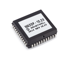
Meanwhile, the PROM Chip installed on a Honeywell VISTA System sets its firmware. You can easily locate the PROM Chip on your VISTA System's green circuit board. Just look for the small black square chip with the white sticker on it. The white sticker includes version information so the user can identify the type of VISTA System they are using and its current firmware. Users remove older PROM Chips and replace them with newer ones as a means of upgrading their VISTA Systems to support new features. Alarm Grid sells 15P PROM Chips, 20P PROM Chips, and 21iP PROM Chips for Honeywell VISTA Systems. We typically advise replacing a 15P or 20P PROM Chip with less than Firmware Version 9.12, as that is the minimum version needed to support Total Connect 2.0. Likewise, the minimum PROM Chip needed on a VISTA-21iP for Total Connect 2.0 is 3.13. For more information on replacing PROM Chips, please see this helpful FAQ.

Please note that it is only possible to replace a PROM Chip on a VISTA System with a firmware version or PROM Chip version of 2.0 or higher. If your VISTA System shows a PROM Chip version of less than 2.0, then it is not possible to replace its PROM Chip, and you must replace the panel entirely. Also note, that you should never attempt to remove or replace a PROM Chip while your VISTA Panel is powered on. Always power down the panel completely before replacing its PROM Chip.

For the longest time, it was believed that you could use an SIA PROM Chip on its non-SIA VISTA printed circuit board (PCB) without experiencing an issue. For example, if you removed the PROM Chip on a Honeywell VISTA-20P, and replaced it with a WA20PSIA PROM Chip, then it was believed that no issues would occur. The same was believed to be true if you used a non-SIA PROM Chip on an SIA-compliant VISTA board. An example there would be if you removed the PROM Chip on a Honeywell VISTA-20PSIA and replaced it with a 20P PROM Chip. Aside from determining what was allowable within programming, no other issues were believed to occur if you used an SIA PROM Chip on a non-SIA VISTA System PCB, or vice-versa.

But upon further testing, that is not the case starting with VISTA System Firmware Version 9.17 on VISTA-20P Panels. Any Honeywell VISTA-20P PCB (non-SIA) that is being upgraded to Panel Firmware Version 9.17 or higher must have a non-SIA 20P PROM Chip. Likewise, any Honeywell VISTA-20PSIA System PCB (SIA-Compliant) that is being upgraded to Panel Firmware Version 9.17 or higher must have a 20PSIA PROM Chip. If you try to use an SIA PROM Chip on a non-SIA VISTA System (or vice-versa), then it is possible that peripheral devices connected to the system's ECP bus may not work properly. ECP devices for a VISTA System include any wired keypads, any alarm monitoring communicators, and any wireless receivers. This same error is also believed to occur on any Honeywell VISTA-15P (or VISTA-15PSIA) that is being upgraded to Panel Firmware Version 9.17 or higher, though further testing is needed to verify if that is indeed the case.

You can determine whether your VISTA System is an SIA Panel PCB or a non-SIA Panel PCB by checking a sticker on the panel's terminal block. This is a small barcode sticker at the bottom of the terminal block, below the phone line terminals. Check for one of the following messages:

  • SAVS20PSIA - Regular VISTA-20P
  • SAV20P-SIAP - VISTA-20PSIA
  • SAVS15PSIA - Regular VISTA-15P
  • SAV15P-SIAP - VISTA-15PSIA

Long story short, if you are using a Honeywell VISTA-20P, VISTA-20PSIA, VISTA-15P, or VISTA-15PSIA and you wish to PROM upgrade it to System Firmware Version 9.17 or higher, then make absolutely sure to use a PROM Chip specifically designed for that particular board. Do not attempt to use an SIA-equivalent on a non-SIA board, or a non-SIA Chip on an SIA-Compliant VISTA board. Mixing an SIA Chip on a non-SIA board (or vice-versa) for 15P or 20P Systems (or SIA equivalents) when upgrading to Firmware Version 9.17 or higher can result in ECP devices not working properly. As long as you use a proper PROM Chip for your system, then no issues should arise. If you are ordering a PROM upgrade chip from Alarm Grid then place your order and be sure to specify which version you need by sending us an email using the email address listed below. If you purchase either the Honeywell LTEIA-TC2 or LTEIV-TC2 or any of our other upgrade kits for VISTA panels, then you will receive all four of the available upgrade chips. Just be sure to select the correct chip for your VISTA PCB.

If you have any further questions about Honeywell VISTA Systems and their PROM Chips, or if you want to learn more about alarm monitoring service for your Honeywell VISTA System, please send an email to support@alarmgrid.com. We're here to answer any questions or concerns you might have. Our hours for responding to emails run from 9am to 8pm ET M-F. We look forward to hearing from you!

Tags: , , , , , , , , , ,

Comments


Posted By

There is currently a big push within the security industry to update the regulations and standards associated with central station monitoring. Many monitoring centers are pressing for key regulatory changes that will allow central station operators to work from home on a permanent basis.


Anyone familiar with central station monitoring knows that there are many policies and rules that govern central stations and their operation. Any certified and accredited monitoring center must adhere to these guidelines, or else they are subject to fines, penalties, and other repercussions. In the United States, such policies are largely authored by Underwriter's Laboratories (UL), a Nationally Recognized Testing Laboratory (NRTL) that wields significant authority over the security industry.

You may recall back in August of last year, it was learned that UL was working to revise the UL-827 Standard for Central-Station Alarm Services. The changes were being made to facilitate remote workers during any "disruption event" that warrants the use of off-site monitoring. Now, many monitoring centers are pushing for policy changes that will allow operators to work from home not only during a so-called "disruption event", but at all times.

Most alarm monitoring centers have reportedly been pleased with the transition of their operators from a traditional monitoring center environment, to a non-traditional home office environment. As one might expect, there are many challenges associated with the changes. While central station operators can be easily seen and supervised in a traditional monitoring center, supervising an employee from home is much more challenging, or even downright impossible.

With possible changes on the horizon, here are some ways that we might see the UL-827 standard updated to accommodate central station operators working from home:

  • Work space updates to ensure that operators cannot have their screens viewed by unauthorized parties. There must also be updates to minimize the noise distractions that can occur in a home office environment. This will require auditing methodologies to ensure that these standards can be consistently maintained.
  • Power requirement updates that may require at-home workers to have backup power supplies to remain operational during electrical outages. This might not be required if the operators are strategically placed in such a way that regional outages should not have a big impact on the performance across the entire monitoring center.
  • Data protection and privacy updates to protect customers. This will likely involve methods of encryption and multifactor authentication. It may be necessary to implement some backup protection measures against data breaches and possible vulnerabilities.
  • Automation updates to ensure that any customer or end user who becomes disconnected from an operator is automatically rerouted to another operator who can assist with the situation. There must also be auditing and reporting requirements to keep track and record when this happens and the resulting action(s).

It must be stressed that even if UL-827 is updated to facilitate permanent at-home operation, not all monitoring centers will change their current operating procedures. Really, it will come down to the discretion of the monitoring centers on how they want to proceed moving forward. The proposed changes to UL-827 will provide monitoring centers greater flexibility in how they conduct business moving forward. In other words, while some monitoring centers may embrace these changes and allow their workers to operate from home, other monitoring centers will likely proceed with no changes and require their staff to continue operating from the central station.

Alarm Grid has not received any word from Criticom Monitoring Services (CMS) regarding any changes they may make in response to updates of UL-827. CMS serves as the central station for all Alarm Grid monitored customers who receive central station monitoring service in the United States. If you have any questions about CMS, or if you are interested in starting new monitoring service, send us an email at support@alarmgrid.com. We will be happy to answer any questions you might have. Our support hours for checking emails run from 9am to 8pm ET M-F. We look forward to hearing from you!

Tags: , ,

Comments


Posted By

Qolsys recently released a Technical Service Bulletin outlining an issue with the IQ2 and IQ2+ panels and PowerG sensors. In some cases, panels that have just installed either firmware version, or panels running these versions that are rebooted, may lose touch with existing PowerG sensors.

The problem, according to Qolsys, is the encryption key. In some rare cases, either during the reboot after the firmware update, or upon rebooting once the firmware update has been applied, the panel's encryption key can be set back to default. Once this occurs, any PowerG devices in the field that have been programmed into the panel will no longer be able to communicate successfully with the panel.

When this situation occurs, a previously working PowerG device will show status on the panel, and on Alarm.com if monitored, of "Not Networked". It may also show an "!" next to the zone's status on the panel's Home Screen. If this condition is allowed to continue for the full supervisory window of the sensor (24-hours for non-life safety sensors, 4-hours for life safety sensors by default) then each affected sensor will go into supervisory failure at the panel and will show a status of Malfunction when viewed through Alarm.com.

If you see this issue on your Qolsys IQ Panel 2 or IQ Panel 2 plus system, you'll need to delete ALL PowerG sensors from the panel, and then re-learn them from scratch. By doing so, a new encryption key will be created and shared with each PowerG device. Once this has been done, all devices should begin working normally again. PowerG devices should be reprogrammed from the panel, not from Alarm.com. This way, full functionality can be verified once programming is complete. It would be best to be sure the panel does not reboot again until the next firmware update, which will resolve this issue. Only PowerG devices are affected by this anomaly, any legacy RF devices using the 319.5MHz, 345MHz, or 433MHz frequencies, and any Z-Wave devices should not be affected by this issue.

If you haven't updated to 2.5.3 or 2.5.4 yet, it is recommended that you update locally at the panel, rather than through Alarm.com. You can find information on updating via Patch Tag or MicroSD card on our Qolsys IQ Panel 2 Plus Firmware Update Page. Sadly, this won't necessarily prevent this issue from happening, but by being onsite at the time of the update, you'll be able to verify proper PowerG sensor functionality on each of your sensors as soon as the update has completed. According to Qolsys, firmware version 2.5.5 will be released in the near future, though an exact date has not been provided. This version will resolve the root cause of this encryption key issue. Any additional future updates will also include the necessary fix.

If you're interested in no-contract, low-cost monitoring, or if you're an Alarm Grid customer (present or future) with questions, you can reach us at support@alarmgrid.com. We're here to check emails M - F from 9:00 am to 8:00 pm Eastern Time. Thanks for reading, stay safe!

Tags: , , , , , , , , , , , , , , , , , , , , , , , , , ,

Comments


Posted By

Alarm Grid is updating all of our monitored 2GIG GC2 panels. If the panel has a firmware version older than 1.19.3.1 and it needs a new communicator, then an over-the-air (OTA) update will be pushed to update it to 1.19.3.1 which will support any LTE comm. The update will cause a reboot.

Alarm Grid is committed to making sure none of our customers are left behind when the AT&T 3G and Verizon CDMA sunsets occur. Toward this goal, we have decided to proactively push a firmware update to each of our customer's 2GIG GC2 panels that are monitored through Alarm.com. The 2GIG GC2 can be a little tricky to update, and pushing the update OTA is by far the easiest way to accomplish this task.

If you are an Alarm Grid monitored customer who has a 2GIG GC2 panel on Firmware 1.19.3.1 or older with a pre-LTE communicator, you won't need to do anything special. The update will be pushed from the Alarm.com server and should occur automatically the next time your system is disarmed with no trouble conditions. As a part of the update, the panel will perform a reboot, and when it boots back up, it is likely to speak the current status. This is a normal part of the update process.

If you'd like to check the firmware version of your system then follow these steps. The purpose of this particular upgrade is to be sure any customer with a panel that doesn't currently support an LTE communicator will be able to do so. If your system already has an LTE communicator, even if the panel is not on the most recent Firmware, then no update will be sent. This is because you already have a Firmware version that supports the LTE communicator you're using.

Here's a breakdown of the 2GIG GC2 Firmware requirements:

Cellular Module Type Panel Firmware Required
Verizon LTE or VoLTE (2GIG-LTEV-A-GC2)

Note: This communicator is no longer available

1.17+
Verizon LTE CAT1 (2GIG LTEV1-A-GC2)

Note: This module is available only to United States Customers

1.19+
AT&T LTE (2GIG-LTEA-A-GC2) 1.19.3+

As always, if you have any questions the best way to reach us is by emailing support@alarmgrid.com. Remember that our support hours are M - F from 9:00 am to 8:00 pm Eastern Time. We offer no-contract monitoring at reasonable prices and world-class technical support to our monitored customers. We look forward to hearing from you!

Tags: , , ,

Comments