The First Alert brand, by Resideo, recently unveiled three new camera models, marking their first camera release in years. The VX Series includes an indoor camera, an outdoor camera, and a video doorbell. These cameras are designed to enhance end-user security and work with Total Connect 2.0.
There are a ton of cameras on the market, and it can be tough to decide which camera or system is right for you. So, we wanted to take a moment and highlight the features of these relatively new First Alert VX cameras. One of the biggest reasons to choose these cameras is that they are compatible with Total Connect 2.0. This is Resideo's remote access platform.
These days, if you can't control an electronic device from anywhere using a smartphone app, you're doing something wrong. From monitoring your pool's water temperature to receiving a notification from your refrigerator to pick up milk, the Internet of Things (IoT) has changed how we do nearly everything.
With that in mind, one of the features to scope out when looking for a security system, camera system, or combination of both is how you interact with that system remotely. For the VX Series cameras and most Resideo or Honeywell panels, remote control is achieved using Total Connect 2.0.
To quickly connect the dots, Resideo, formerly Honeywell, owns the First Alert Professional brand. They also own AlarmNet, which provides the network through which most Resideo, Honeywell, Honeywell Home, and First Alert Professional products communicate when using WIFI, ethernet, or cellular devices. Most communicators are sold under the AlarmNet brand. However, all of these brands, except for a few currently produced Honeywell products, live under one big Resideo umbrella.
Here's an example of what happens with an alarm on one of these panels.
For this example, we'll assume you have a Honeywell Home PROA7PLUS panel with a WIFI and cellular communicator. With this system, you have central station monitoring and Total Connect 2.0:
- An alarm that requires a notification to the end-user, a report to a central station, or both occurs.
- The PROA7PLUS transmits the alarm signal. It will use WIFI if available, and cellular if WIFI is down.
- The signal travels through the network (WIFI) or the carrier (cellular) to a server at AlarmNet. The carrier may be AT&T or Verizon within the US. It could be Rogers or Telus in Canada.
- Based on the MAC address of the communicator where the signal originated, the AlarmNet server matches the signal with an account and forwards the alarm information to the proper central station. With Total Connect 2.0, a notification will also be sent to the end-user, if enabled. Steps 1 - 4 occur within seconds.
- The central station processes the signal according to its policies and any instructions provided by the end-user.
The VX Series cameras can be used with Total Connect 2.0 on a stand-alone video account, or, in conjunction with a security system. Here at Alarm Grid, we offer our Platinum Plans (Self or Full) which include security, remote control with automation, and video, or our stand-alone Video Monitoring plan which can be used without a security system.
Any plan that includes cellular communication also includes IP (WIFI or ethernet) at no additional cost. Each video plan allows up to eight (8) cameras. The smart camera package will allow up to 50 clips per day, per camera. Video for the VX camera lineup is stored on the TC2 server for 30 days.
First Alert Pro VX1 HD Video Doorbell
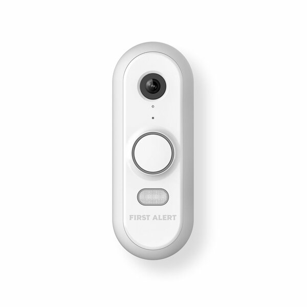
The First Alert Pro VX1 HD Video Doorbell (SKU: CAMW-WDB) boasts a 5MP camera, 2-way audio, dual-band WiFi, and intelligent event detection. Its advanced AI can accurately distinguish between people, packages, vehicles, and animals minimizing nuisance notifications and recordings.
Equipped with a built-in LED, color night vision, and a siren that can be manually activated, the VX1 doorbell offers enhanced security. Its wide dynamic range (WDR) technology uses both hardware and software to ensure vibrant color and high-quality video, even in challenging lighting conditions.
The VX1 HD comes with some nice accessories. It offers a trim ring in either gray or white. It can be mounted with either a straight or an angled mounting bracket A mechanical chime adapter is included, along with a doorbell release/reset tool, and mounting hardware. The VX1 is made of UV-resistant material to withstand harsh sunlight and other outdoor elements.
First Alert Pro VX1 HD Data Sheet
First Alert Pro VX1 HD Install Guide
First Alert Pro VX1 HD Specifications:
-
Device Type: Video Doorbell Camera.
-
Compatibility: Total Connect 2.0 Video Plan REQUIRED. Each VX1 counts as one camera when used with any video plan.
-
Power Requirements: 16 VAC to 24VAC, 10VA minimum.
-
Chime Compatibility: Mechanical and Digital Chimes with included Chime Adapter.
-
Speaker: 93dBA @0.1m
-
Microphone: 10ft (3m)
-
Camera: 5MP
-
Video Resolution: 2592 x 1944 Full HD
-
Video Format: H.264
-
Diagonal Field of View: 180°
-
Available Fields of View: Tall, Wide, and Full
-
Wide Dynamic Range (WDR): Yes
-
IR Night Vision: up to 23' (7.01m)
-
Color Night Vision: Up to 10' (3m).
-
Image Adjustments: Low or High Quality.
-
Motion Detection: Yes, up to four (4) windows. Optional selections to detect people, vehicles, and/or animals.
-
Two-Way Audio: Yes
-
Clip Viewing: Via TC2 (app & website)
-
Privacy feature: Yes, available via the TC2 app. Selected manually, or by the option to "Turn on camera privacy when security is disarmed."
-
Emergency/Panic: Yes, while streaming only
-
WIFI Specs: Dual-band, 2.4 GHz or 5 GHz
-
Bluetooth: BLE 5.0
-
Ingress Protection: IP65 (dustproof and water resistant)
-
UV Resistant: Yes
-
Dimensions: 4.8" x 1.8" x 1.1" (120.7mm x 44.5mm x 28.5mm)
-
Weight: 5 oz (144g)
-
Operating Temperature: -40°F to 122°F (-40ºC to +50ºC)
-
Operating Relative Humidity: 20% to 85%, Non-condensing
-
Included Accessories:
- Gray Mounting Brackets (Both Straight and Angled)
- Both White and Gray Trim Rings
- Chime Adapter
- Mounting Hardware
- Mounting Brackets
- Quick Install Guide
First Alert Pro VX3 HD Outdoor Camera

The First Alert Pro VX3 HD Outdoor Video Camera (SKU: CAMWE-WO) has intelligent event detection allowing it to identify people, animals, vehicles, and packages. It also features a microphone for sound detection, and a speaker for 2-way communication through the camera. New to the First Alert camera line, is an option to use Power-Over-Ethernet (PoE) connection. All this is included in an attractive HD camera.
The VX3 also has a built-in, manually-activated deterrent feature. While viewing a live feed from the First Alert Pro VX3, through TC2 or a PROSeries panel, the user can tap the siren icon to initiate a 93 dBa siren and an LED spotlight produced by the camera. This manual activation can aid in scaring off potential intruders.
With its IR night vision, the VX3 can be programmed for full-time color night vision or color on detection only. Color on detection allows infrared to handle night-time viewing until a recording is triggered. Then, the camera will automatically switch to color night mode. If color night vision is set to always on, the LED light ring will be lit constantly during the night.
The VX3 HD is a Total Connect 2.0 (TC2) camera. A TC2 smart video account is required to enroll and use it. As mentioned when describing the VX1 HD, this means a Platinum (Self or Full) or Video Monitoring plan for Alarm Grid customers. Each VX3 will count as one (1) camera in the video package. Each video plan allows up to eight (8) cameras. The smart camera package will allow up to 50 clips per day, per camera. Video is stored on the TC2 server for up to 30 days.
First Alert Pro VX3 HD Outdoor Camera Data Sheet
First Alert Pro VX3 HD Outdoor Camera Install Guide
First Alert Pro VX3 HD Outdoor Camera Specifications:
-
Device Type: Outdoor HD Camera
-
Compatibility: Total Connect 2.0 Video Plan REQUIRED. Each VX3 counts as one (1) camera when used with any video plan.
-
Power Requirements: 12VDC @ 1A Power Adapter or 802.3af PoE Class 3 PSE.
-
Transformer Wire Length: 10' Max (3.05m)
-
POE length: 300' (100m) Max
-
Speaker: 65dBA @3m, 1kHz
- (low, medium, or high adjustment via app)
-
Microphone: 10' (3m)
-
Camera: 2MP
-
Video Resolution: 1080p Full HD w/ Wide Dynamic Range (WDR)
-
Video Format: H.264
-
Diagonal Field of View: 147°
-
Ceiling Mount Option: Yes, Flip orientation 180°
-
Wide Dynamic Range (WDR): Yes
-
IR Night Vision: up to 23' (7m)
-
Color Night Vision: up to 10' (3m)
-
Image Adjustments: Low or High Quality
-
Motion Detection: Yes, Up to Four (4) windows. Optional AI selections to detect people, vehicles, packages, and/or animals.
-
Two-Way Audio: Yes
-
Clip Viewing: Via TC2 (App & Website)
-
Privacy Feature: Yes, available via the TC2 app. Selected manually, or by the option to "Turn on camera privacy when security is disarmed."
-
Emergency/Panic: Yes, Only While Streaming.
-
Firmware Upgradeable: Yes, Auto-updates
-
Ethernet Specs: WIFI or Hardwired (If both are used, Ethernet is primary)
-
WIFI Specs: Dual-band, 2.4 GHz or 5 GHz
-
Bluetooth: BLE 5.0
-
Ingress Protection: IP66 (dust-proof and water-resistant)
-
UV Resistant: Yes
-
Dimensions: 3" x 3" x 5" (76.2mm x 76.2mm x 127mm)
-
Weight: 5oz (144g)
-
Operating Temperature: -40°F to 122°F (-40ºC to +50ºC)
-
Operating Relative Humidity: 10% to 85%, Non-condensing
-
Included Accessories:
- Mounting hardware
- Mounting Brackets
- Quick Install Guide
First Alert Pro VX5 HD Indoor Camera
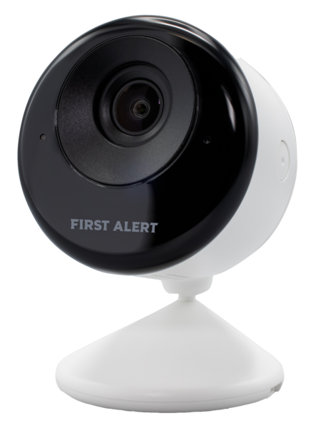
The First Alert Pro VX5 HD Indoor Camera (SKU: CAMW-WI) is an HD quality, indoor video camera. It allows users to monitor the interior of a home or small business using a combination of live and recorded video. Users can keep an eye on their kids, elderly family members, pets, or guests with razor-sharp 2K resolution and superb night vision.
The First Alert VX5 HD is equipped with advanced event detection capabilities. Using AI, it can determine whether a person, an animal, or a vehicle is within its field of view, allowing it to deliver precise and meaningful notifications. Each camera can have up to four (4) event detection areas configured.
This indoor camera captures 1080p video while allowing the user to ensure privacy with an automated privacy shield. Privacy can be controlled by either pressing a button on the side of the camera or through the Total Connect 2.0 App. If an admin user in TC2 sets the camera for privacy a standard user cannot change this setting. It can also be set to enable privacy when the alarm system is disarmed.
The camera integrates with the PROA7PLUS or PROA7PLUSC panel and the PROWLTOUCH and PROWLTOUCHC wireless touchscreens, offering on-screen video streaming. The VX5 also has a microphone and speaker and supports 2-way audio between a user in Total Connect 2.0 and the camera.
The emergency button option is also available for the VX5. If you see an intruder while live-streaming video, you can press an emergency icon within the TC2 app and the camera's LED will turn on and its siren will sound. At 70 dB @ 3.2' (1m) this siren won't harm an intruder, but it will get their attention.
First Alert Pro VX5 HD Indoor Camera Data Sheet
First Alert Pro VX5 HD Indoor Camera Install Guide
First Alert Pro VX5 HD Indoor Camera Specifications:
-
Device Type: Indoor HD Camera
-
Compatibility: Total Connect 2.0 Video Plan REQUIRED. Each VX5 counts as one (1) camera when used with any video plan.
-
Power Requirements: 12VDC @ 1A. Power Adapter included with 9' (2.7m) wire. Cannot be extended.
-
Transformer Wire Length: 9' Max (2.7m)
-
Speaker: 70dB @ 3' (1m)
-
Microphone Range: 20' (6m))
-
Camera: 2MP
-
Video Resolution: 1920 x 1080 pixels maximum
-
Video Format: H.264
-
Diagonal Field of View: 130°
-
Horizontal Field of View: 111°
-
Vertical Field of View: 59°
-
Wide Dynamic Range (WDR): Yes
-
Night Vision Range: 15' (4.5m)
-
Advanced Detection: Yes, Up to Four (4) windows. Optional AI selections to detect people, vehicles, or animals.
-
Two-Way Audio: Yes
-
Clip Viewing: Via TC2 (App & Website)
-
Privacy Feature: Yes, available via the TC2 app and at the camera. Selected manually, or by the option to "Turn on camera privacy when security is disarmed."
-
Emergency/Panic: Yes, Only While Live Streaming.
-
Firmware Upgradeable: Yes, Auto-updates
-
Network Specs: Dual-band 2.4 GHz or 5 GHz WIFI, IEEE 802.11 a/b/g/n/ac
-
Bluetooth: BLE 5.0
-
Dimensions: 3.5" x 2.25" x 2.5" (89 x 57 x 64mm)
-
Weight: 5.2 oz (148g)
-
Operating Temperature: 32˚F - 104˚F (0˚C - 40˚C)
-
Operating Relative Humidity: 10% to 85%, Non-condensing
-
Included Accessories:
- Power Adapter
- Mounting Hardware
- Quick Install Guide


