June 2018 Archives

Posted By

Honeywell's Total Connect 2.0 service has received a much anticipated update that provides the platform with new functions and capabilities. The new features should currently be live and available for Honeywell users. Both the browser version and the TC2 Mobile App have received the update.

This is version 5.1.2 of Total Connect 2.0. It is an update over 5.1.1, which featured some bugs that Honeywell wanted to correct. With this update, users should find that Total Connect 2.0 will run smoothly and without issue.

The following features are included in the update:

Multi-Partition Support

Users can now access Total Connect 2.0 to control multiple partitions on their compatible Honeywell VISTA Alarm System. Users can access this type of control through the "Partitions" tab within Total Connect 2.0.

The following partition functions are available:

  • Name partitions
  • Arm and disarm individual partitions
  • Bypass sensors
  • Assign partition control to different users
  • Enable or disable event notifications
  • Set remote disarming capabilities for individual partitions
  • Choose which user codes can activate and edit partition settings
  • View activity of fire partitions remotely (cannot control a fire partition remotely)

Please note that users with an existing Total Connect account may not see the Partition tab right away. Honeywell is currently in the process of rolling out this update, and it is slowly being made available to existing users over time. According to Honeywell, all TC2 users with a compatible VISTA Alarm System should be able to access the Partitions tab by June 25th.

For more information on the TC2 multi-partition support, please review this helpful guide.

Amazon Alexa Skill

We previously announced that Amazon Alexa support was available for Total Connect. However, there was no way to control smart scenes through Alexa. But this latest update from Honeywell has made scene control possible.

Honeywell users can now control home automation scenes by providing voice commands to their Amazon Alexa device. Users will be able to ask Alexa to perform any Z-Wave scenes that they have programmed through Total Connect. To use this feature, a user will need to enable the Total Connect 2.0 Alexa Skill on their Android or iOS device.

Here is a video demonstrating the feature:

Multi-Language Support & Stability Fixes

Total Connect 2.0 is now available in French, Spanish and Portuguese. The platform has also received patches to improve overall stability.

If you have any questions about this update, please email us at support@alarmgrid.com, or call us at 888-818-7728 M-F from 9am to 8pm.

Tags: , ,

Comments


Posted By

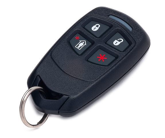
One of the most versatile security key fobs on the market today is the Honeywell 5834-4. This is a wireless four button key fob with up to eight different programmable functions. The device will function from up to 50 feet away from the system. This makes the 5834-4 a convenient tool for quickly arming and disarming your system and performing other useful functions. This helpful guide will tell you everything you need to know about the 5834-4 key fob so that you can fully integrate it into your security setup.


Overview of the 5834-4 and Other 5800 Series Key Fobs

The Honeywell 5834-4 is actually the same security key fob that ADT provides for their monitored customers. This means that an ADT Key Fob can generally be used in the exact same manner as a 5834-4. If an ADT customer decides to leave ADT, they will most likely be able to use their old ADT Key Fob with their new monitoring company. A user can program their old ADT Key Fob with any compatible alarm system, even if the device has not been deleted from the old system. That said, we do recommend deleting the device from the old system if possible.

The 5834-4 is recognized as a wireless sensor from the Honeywell 5800 Series. Just like the other devices in this lineup, the 5834-4 Key Fob operates at a wireless frequency of 345 MHz. It will interface with any control panel that utilizes this wireless frequency. This includes the Honeywell Lyric Controller, Honeywell LYNX Touch Panels, Honeywell VISTA Panels (with an added wireless receiver), the 2GIG GC3 and the 2GIG GC2. In order to achieve the maximum functionality of the device, the 5834-4 will require eight separate wireless zones on the system.

The 5834-4 can perform system commands at a maximum distance of up to 50 feet away from the alarm system, though a Honeywell 5800RP Wireless Repeater can be used to extend this range. Also, any button press that is made using the 5834-4 must be held down for half a second before the programmed action will go into effect. This helps to prevent potential false alarms caused by the key fob.

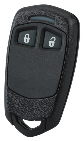
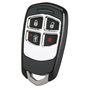
In addition to the 5834-4, Honeywell produces two other key fob devices that are very similar in terms of use. The 5834-2 features two buttons and up to three programmable functions. This two-button key fob is a good option for users who do not require a device with as many functions as the 5834-4. Honeywell also offers the 5834-4EN. This is literally the exact same device as the 5834-4. The only difference is that the 5834-4en features a design with a pleasant silver finish.

Enrolling the 5834-4

Each function on a 5834-4 Key Fob is assigned its own wireless zone on a security system. This means that if every possible button entry is set up, the device will take up eight wireless zones. Each button entry can be learned-in with the security system, much in the same way as any other wireless security sensor. With the panel in its learn mode, press and hold the button entry you want to program. The panel will beep to let you know that it has recognized the key fob. Do this three times to auto-enroll that button press with the system.

Please note that some alarm panels will require you to use the panel's designated "key fob zones" to auto-enroll the 5834-4 with the system. For these panels, attempting to assign the 5834-4 with a non-key fob zone will require that the serial number be entered in manually rather than being learned-in automatically. While the 5834-4 can technically be used with any wireless zone, we always recommend assigning the device to a key fob zone if possible. The exact zone numbers for the key fob zones vary between different alarm panels.

Also note that most panels will have a specific sub-menu within programming for setting up key fobs. By setting up a 5834-4 through this sub-menu, the device inputs will automatically be assigned to a designated key fob zone on the system. Again, we strongly recommend setting up a 5834-4 key fob through the key fob sub-menu for the panel.

The table below outlines the key fob zone numbers for various types of alarm systems:

Panel Type
Key Fob Zones
Honeywell VISTA-15P 49-56
Honeywell VISTA-20P & VISTA-21iP 49-64
Honeywell LYNX Touch 140-147
Honeywell Lyric Controller 131-162
2GIG GC2 51-58
2GIG GC3 32 Key Fob Zones*
*Note: The 32 key fob zones on a 2GIG GC3 are considered separate from other wireless zones.

The 5834-4 uses two different 7-digit Serial Numbers. The second Serial Number is one digit higher than the first Serial Number. So for example, if the first Serial Number is 123-4567, then the second Serial Number would be 123-4568. The first Serial Number is used with all single-button presses, while the second Serial Number is used with multi-button presses. Each unique input is assigned a Loop Number 1-4. This means that each of the eight possible inputs will have a Serial Number and Loop Number combination that is unique from all the others. This is shown in the following diagram:

Note that each button is identified by a different letter. The button in the upper-left corner with the closed lock is Button A. The button in the upper-right corner with the open lock is Button B. The button in the lower-left corner with the person standing inside the house is Button C. The button in the lower-right corner with the asterisk (*) is Button D.

Please note that the button combinations of A+D and B+C are not used with the system. But all other two-button combinations are fair game. Serial Number 2 will be one digit higher than Serial Number 1. The following table outlines every Serial Number and Loop Number combination used with the 5834-4 Key Fob:

Input Serial Number Loop Number
A 1 3
B 1 2
C 1 4
D 1 1
A+B 2 1
A+C 2 3
B+D 2 4
C+D 2 2

Configuring the 5834-4

Once an input has been enrolled with the panel, you must then configure the settings for that input. The exact options for for this will vary depending on the type of panel that is being used. Most options are fairly self-explanatory and can be configured with relative ease. For example, below are the menu options displayed for a Honeywell LYNX Touch L7000, assuming that the device is being programmed through the key fob menu. Please note that these are essentially the same menu options that will also be displayed on any other Honeywell LYNX Touch Panel, as well as the Honeywell Lyric Controller. Make sure to save your changes when you have finished configuring the key fob settings.

  • Key Type: This tells the panel how many different inputs are used on the key fob device. Since a 5834-4 Key Fob with eight different possible inputs is being used, the option "8 button" is chosen.
  • User: This will show in the event log which user interacted with the panel. This is great for assigning different system users their own personal key fob.
  • Serial Number: This is the Serial Number for the key fob. If the Serial Number is entered incorrectly, the key fob will not work with the system. For that reason, we strongly recommend auto-enrolling the 5834-4 with the system.
  • Zone: This is the first zone on the system that the key fob will be assigned to. That zone, and the following seven zones will be used with that key fob.
  • Button Key 1: Button A on the 5834-4. This is the picture of the closed lock. This lets you choose the action that will be taken for that input.
  • Button Key 2: Button B on the 5834-4. This is the picture of the opened lock. This lets you choose the action that will be taken for that input.
  • Button Key 3: Button C on the 5834-4. This is the picture of the person standing in the house. This lets you choose the action that will be taken for that input.
  • Button Key 4: Button D on the 5834-4. This is the picture of the asterisk (*). This lets you choose the action that will be taken for that input.
  • Button Key 5: Button combination A+C on the 5834-4. This lets you choose the action that will be taken for that input.
  • Button Key 6: Button combination C+D on the 5834-4. This lets you choose the action that will be taken for that input.
  • Button Key 7: Button combination B+D on the 5834-4. This lets you choose the action that will be taken for that input.
  • Button Key 8: Button combination A+B on the 5834-4. This lets you choose the action that will be taken for that input.

Also take note of the different possible actions that can be used with each possible input:

  • Disarm: This will disarm the system if the system is set to armed stay or armed away.
  • Arm Away: This will set the system to armed away.
  • Arm Stay: This will set the system to armed stay.
  • No Response: The input will not be used with the system.
  • 24 Hour Silent: This will produce a silent alarm on the system. This essentially allows the 5834-4 to be used as a silent panic switch.
  • 24 Hour Audible: This will produce an alarm event on the system. Any sirens and sounders set up with the system will activate.
  • 24 Hour Auxiliary: This will produce an alarm event on the system. The system sounder will activate, but any sirens will not. This is typically used for medical emergencies.
  • Silent Burglary: This will produce a silent alarm on the system. However, this command will only work if the system is armed.
  • Fire No Verification: This will produce a fire alarm on the system.

Standard Mode vs. High-Security Mode

the 5834-4 Key Fob features two different transmitting modes. These are standard mode and high-security mode. Simply put, standard mode has the 5834-4 function as an unencrypted device, while high-security mode has it function as an encrypted device. Putting the 5834-4 into high-security mode will make it nearly impossible for others to hack or compromise the device. However, high-security mode is only compatible with alarm panels that support this feature. For panels that do not support this feature, the 5834-4 Key Fob must be placed in standard mode before it can be used with the system. Some panels that do not support high-security mode include the 2GIG GC3 and the 2GIG GC2.

To activate high-security mode on the 5834-4 Key Fob, press and hold the A+C+D buttons on the device simultaneously for five seconds. The LED light on the device will flash red to indicate that the device has been placed into high-security mode. Once in this mode, any input made using the 5834-4 Key Fob will cause the LED light on the device to flash red.

To activate standard mode on the 5834-4 KeyFob, press and hold the B+C+D buttons on the device simultaneously for five seconds. The LED light on the device will flash green to indicate that the device has been placed into standard mode. Once in this mode, any input made using the 5834-4 Key Fob will cause the LED light on the device to flash green.

The 5834-4 Battery

The Honeywell 5834-4 Key Fob uses a 3-volt CR2032 lithium battery. Every new 5834-4 comes included with a fresh battery that is already installed. The battery should last for about three to five years before requiring a replacement. As the key fob is used, the power that is supplied by the battery will being to slowly drop. Once the power drops below 2.3 volts, a low battery message will be displayed on the alarm system. Please note that this message will only appear if a button is pressed on the key fob. If the key fob is not used, then the panel will not recognize that the battery is low. Additionally, once the battery is low, the LED light on the key fob will no longer flash when an input is made. If the power drops below 2.0 volts, then the device will stop working entirely.

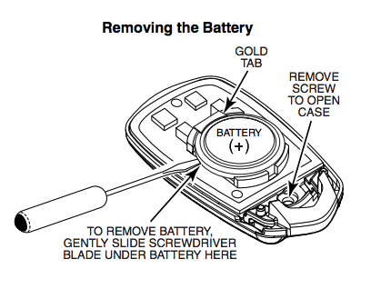
To replace the battery, use a small Phillips head screwdriver to remove the screw on the back of the device. Then slide a flathead screwdriver underneath the battery on the side with the gold tab to pop the battery out. With the old battery removed, slide the new battery into place, making sure that the positive (+) side is facing upwards. Firmly press down on the opposite side to click the battery into place. Finally, reapply the back cover, and screw it into place. Make sure to test the 5834-4 Key Fob after replacing the battery to ensure that it has been installed properly.


If You Need Further Help

The Alarm Grid support team is happy to help any monitored customer with using their 5834-4 Key Fob. Please contact us via email at support@alarmgrid.com or over the phone at 888-818-7728 from 9am-8pm ET M-F if you require further assistance.

Tags: , , , , , , ,

Comments


Posted By

After much anticipation, partition support for Total Connect 2.0 will soon be available for compatible VISTA Systems! With this update, users will gain full access to each live system partition. This includes controlling, checking the status and receiving updates for individual partitions.

The TC2 partition update applies to the following panels:

  • VISTA-20P
  • VISTA-20PSIA
  • VISTA-21IP
  • VISTA-21IPSIA
  • VISTA-128BPT
  • VISTA-128BPTSIA
  • VISTA-250BPT
  • VISTA-128FBPT
  • VISTA-250FBPT
  • VISTA-32FBPT

By using TC2, users can control up to eight different partitions on their alarm system. However, if their VISTA System supports fewer partitions, the user will only be able to control the number of partitions that are supported by their respective system (e.g. VISTA-20P can only support three partitions, with one being a common partition). With this update, users with compatible systems will be able to perform the following functions from Total Connect 2.0:

  • Name partitions
  • Arm and disarm individual partitions
  • Bypass sensors
  • Assign partition control to different users
  • Enable or disable event notifications
  • Set remote disarming capabilities for individual partitions
  • Choose which user codes can activate and edit partition settings
  • View activity of fire partitions remotely (cannot control a fire partition remotely)
  • Additional features to be announced

To ensure a successful rollout, Honeywell is making partition support available for a small percentage of customers each day. The process already started on Monday, June 11th, and it is expected to continue until the week of June 25th. By the week of June 25th, all compatible VISTA Systems should have TC2 partition support. Also note that any new Honeywell Total Connect VISTA partition account programmed during the rollout will be enabled for partition support the next regular business day.

Sometime during this rollout period, you should notice an update on your Total Connect 2.0 account. The message will state that partitions for your location have been made available. You will then be able to configure the partitions for your VISTA System through both the Total Connect 2.0 web browser and the TC2 Mobile App.

Please note that you will not be required to set up multiple partition configurations for your system right away. You can also choose to save the set up process for a later time. To configure partitions for your system immediately, select "Configure Now". To save the process for another time, choose "Later". You will be able to access partition support by clicking the "Partitions" tab on Total Connect 2.0.

To learn more about this feature, please review this helpful guide from Honeywell.

If you have any questions about Total Connect 2.0 partition control, please do not hesitate to contact us at support@alarmgrid.com or call us at 888-818-7728 from 9am to 8pm M-F.

Tags: , , , , , , , , , , , ,

Comments


Posted By

Not every building that receives monitoring service is a traditional home or business. Alarm monitoring services are often provided for abandoned or vacant buildings. This is done to monitor the premises and make sure that no unwanted intruders are present. Just a few simple sensors and a basic monitoring setup will allow you to protect an abandoned or vacant building.

People break into abandoned buildings for a number of different reasons. Some people vandalize these properties to steal any scrap or other building materials that they come across. Others may try and occupy the building as a shelter, or they might cause intentional damage to the structure. Regardless, you will want to do everything possible to keep these intruders out.

For abandoned buildings, there are a few different sensor types that are particularly useful. You may want to use door and window contacts to monitor any easily accessible doors and windows. Motions sensors are critical, as they will allow you to scan the building for any intruders. We recommend placing motions in key central areas so that anyone on the premises can be quickly identified. You may also want to install glass break detectors to listen for any window breakages that may occur.

Most abandoned buildings will not have WIFI or some other form of connectivity. For that reason, cellular service is absolutely necessary for monitoring a vacant building. This type of communication is extremely reliable, and it provides very fast connection speeds. Cellular connections are also nearly impossible for others to tamper with, and they are not affected by power outages. However, it is important to remember that you will still need to provide power to the alarm system as a whole. Monitoring a building without electricity is not currently possible.

Just because a building is unoccupied does not mean that it cannot benefit from alarm monitoring. Protect your unoccupied building with Alarm Grid monitoring services. You may reach us at support@alarmgrid.com or by calling us at 888-818-7228 between the hours of 9am and 8pm EST M-F.

Tags:

Comments


Posted By

Just last week, millions of US Comcast customers experienced issues with their landline telephone service. The outage occurred during the morning of Wednesday, June 6th. During this time, these users were unable to place or receive phone calls using their standard telephone service.

According to outage maps, the problem occurred throughout the country. The cities of San Francisco, Chicago, Portland, Mountain View, Denver, Seattle, Atlanta, Houston, New York, and Philadelphia were notably affected. Perhaps more troubling is that several emergency services were down, including certain police and fire departments in New Hampshire.

This is an important reminder to all regarding the risks of using POTS (plain old telephone service) with an alarm system. Not only is POTS connectivity slow, it also quite unreliable. Many signals sent out from an alarm system through a telephone line fail to go through properly. This can be incredibly dangerous during an emergency. Additionally, an intruder can potentially cut a phone line to prevent the system from working properly.

That is why we encourage all our users to sign up for cellular monitoring. Most security experts agree that cellular service is the optimal communication path for an alarm system. Cellular communication is extremely reliable, with the service almost never being down or unavailable. It is unaffected by power outages, and it is next to impossible for an intruder to tamper with the connection. Additionally, the LTE cellular speeds of today are right on par with those of WIFI connectivity.

Cellular monitoring will allow allow you to connect your system with an interactive service platform, like Total Connect and Alarm.com. These services can be accessed at any time to operate an alarm system. By accessing their service, a user can arm and disarm their system, check the current status of sensors, control Z-Wave devices, view their security cameras and more. And with the service's mobile app, these actions can be performed from virtually anywhere with your smartphone.

To get cellular monitoring, you will need a panel with a cellular communicator and an alarm monitoring plan that includes cellular service. For Alarm Grid, these are our Gold and Platinum level plans. For more information, please check out our monitoring page. If you want to get started with monitoring, please email us at support@alarmgrid.com, or call us at 818-888-7728 from 9am to 8pm M-F.

Tags:

Comments


Posted By

Hi DIYers! We would like to announce that Alarm Grid has created a special Alarm.com test account for new customers. Anyone can access this account to test out the exciting features and capabilities of Alarm.com. This can help you decide if the Alarm.com service platform is right for you.

This account can be accessed even if you do not have your own Alarm.com account. By accessing this test account, you can see what Alarm.com is like before you actually obtain the service for yourself. Existing Alarm.com customers may want to access this test account so that they can try out different settings without messing with their own configurations. This test account is also useful for users who are new to Alarm.com and want to learn how to properly use the service.

To access this test account, go to https://www.alarm.com/login. Then provide the following information:

Username: AGCust@alarmgrid.com

Password: AlarmGrid123

Please note that the password is cAsE sEnSiTiVe, and A and G in AlarmGrid123 must be capitalized.

If you have any questions about this account, or if you are having trouble accessing it, please send us an email at support@alarmgrid.com.

Tags: , ,

Comments


Posted By

It's the rainy season once again, and one thing you will certainly want to do is monitor your house for floods. This is done using flood sensors. These sensors will send an alert to the alarm system upon detecting water. This can help you detect a flood before serious damage occurs.

2gig ft1 345 flood and temperature sensorFlood sensors typically operate using a water probe. On these probes, there are pins that will cause the sensor to activate when they come into contact with water. Depending on the type of sensor, the pins may need to be exposed to water for a couple of minutes before the sensor will activate and an alarm will occur. This can be helpful for reducing false alarms and only alerting the system when there is a real flooding concern. Some probes come already attached to sensors. Others, like the Honeywell 470PB, will need to be wired to a separate sensor.

For best results, a flood sensor should be installed in a location where a flood is mostly like to occur. This can include basements, kitchens, laundry rooms and bathrooms. It is also a good idea to place these sensors underneath water heaters and sump pumps that could leak and cause serious damage. The earlier that the sensor is activated, the quicker that you can be alerted to the issue and properly solve the problem.

Flood sensors are excellent devices to pair with an interactive service such as Total Connect or Alarm.com. If the flood sensor activates while you are away from home, you will want to know about it as soon as possible. These services can send you text and email notifications as soon as a flood sensor activates. This way, you or a trusted neighbor can properly deal with the issue as soon as it happens. You may be able to stop the flooding before there is serious property damage.

When choosing a flood sensor, you must make sure it is compatible with your alarm system. This is especially true if you are using a wireless flood sensor. You will want to know which wireless frequency is used with your system and which type of wireless sensors are compatible.

Alarm Grid recommends the following wireless flood sensors for these different systems:

Qolsys iq flood flood sensor for the qolsys iq and iq panel 2 qs

Tags: , , , , , , , , ,

Comments


Posted By

One of Alarm Grid's best partners Qolsys has announced that their upcoming IQ Panels with PowerG support have officially received UL certification. It appears as though the company is currently on track to have these new systems ready for a public release later this summer season.

PowerG is a wireless sensor lineup from DSC. These are state-of-the-art security sensors that boast some highly impressive capabilities and features. They operate at a considerably higher frequency (915 MHz) than most other wireless sensors, meaning that they will not interfere with other devices. The range of these sensors is absolutely insane, as they can operate from nearly half a mile away from the panel when used indoors. The sensor also use 128-bit AES encryption to prevent them from being hacked or spoofed. Needless to say, we are very excited that Qolsys Systems will soon be able to support these sensors.

Qolsys previously announced at ISC West 2018 that a PowerG daughtercard would be made available for their IQ Panel 2. By installing this daughtercard, the system will be able to support PowerG sensors. Qolsys will also likely produce IQ Panel 2 Systems with the daughtercard already integrated, and also possibly other PowerG-compatible systems as well. So far the PowerG lineup includes outdoor PIR motion detectors with integrated cameras, outdoor siren/strobe devices and a door contact with a wired input for long-range expansion.

ISC West 2018 was also when Qolsys announced that they would soon be offering legacy daughtercards for the IQ Panel 2. These daughtercards are available in 319.5 MHz (Qolsys and Interlogix/GE Sensors), 345 MHz (legacy Honeywell and 2GIG Sensors) and 433 MHz (legacy DSC Sensors). Please note that the system will only support one PowerG daughtercard and one legacy daughtercard at any given time.

Alarm Grid will make sure to keep you up to date with any of the latest news regarding Qolsys and PowerG support. Keep an eye on our blog for more information.

Tags: , , , , , , , , , , , ,

Comments


Posted By

Not every opening is conveniently located inside the house. A user may also want to monitor openings that are located outside the house. This could include fences, detached garage doors, barns and patio doors. When doing this, the sensor must be able to survive the outdoor environment.

Durability is a much greater concern with outdoor contacts. While most contacts are kept safe inside the home, an outdoor contact is exposed to a much harsher environment. The sensor will need to work in more extreme temperatures, and it will come into contact with water and dust on a regular basis. Needless to say, if a user tries to use a standard contact, it will not last very long.

Luckily, there are special outdoor contacts that are specifically designed to survive in an outdoor setting. These contacts typically function in the same manner as an indoor contact, using a sensor and magnet. The sensor is installed on the stationary portion of the opening, while the magnet is installed on the moving part. The magnet must be placed very close to the sensor in order for this process to work properly.

When the outside door or fence is opened, the magnet will separate from the sensor. This will cause a reed switch inside the sensor to activate. The sensor will then send a signal to the alarm system to let it know that it has been activated. When this happens, the system can then perform a pre-programmed response. This could include requiring a system disarm or sending out an alarm to a central station.

One excellent outdoor sensor for this purpose is the Honeywell 5816OD. This is a 345 MHz wireless sensor that will work with any Honeywell or 2GIG Alarm System. It is fully weatherproof, and it can survive temperatures ranging from -40° to 150° Fahrenheit. The sensor will continue to function properly, even in a very dusty or humid environment. For best results, the sensor should be placed within 1.5" of the included magnet when the opening is closed.

Honeywell 5816od wireless outdoor door and window sensor top

You can purchase this sensor from the Alarm Grid website. If you have any questions about using this sensor, you may contact us via support@alarmgrid.com or by calling us at 888-818-7728 between 9am and 8pm M-F.

Tags: , ,

Comments


Posted By

Hi DIYers! Our technical support team has been producing new videos to help others learn how to use their security systems. We've already received great feedback on our videos, and we look forward to making more. Let's take a look at some of the videos that we've released in the past week.

Using Wired Contacts on a 2GIG GC3

Joe explains how to use hardwired contacts with the 2GIG GC3 System. There are a few different ways of doing this. The GC3 actually has built-in support for two different hardwired sensors. If a user needs to use additional wired contacts, they can do so using a compatible wired to wireless converter, such as a Honeywell 5800C2W or a 2GIG TAKE-345. It is also possible to connect the wired contact to a wireless transmitter that will send signals to the panel on the sensor's behalf.


Getting Monitoring for a Self-Installed 2GIG GC3

Joe talks about how it is possible to receive monitoring service for a 2GIG System that has been self-installed. These systems can connect with the Alarm.com interactive service platform by receiving cellular monitoring. This requires a compatible cellular communicator and a cellular alarm monitoring plan. The cellular module includes a serial number that is needed for activating the system. The system will need to be activated by the user's alarm monitoring company in order for the system to receive active monitoring service.


Using the Lyric Alarm System as a Secondary Z-Wave Controller

Joe discusses how the Honeywell Lyric Controller can be used to operate Z-Wave home automation devices. By using the Lyric as a secondary controller in conjunction with a primary Z-Wave controller, the Z-Wave network will be able to perform more advanced functions. When doing this, Z-Wave devices should be learned-in with the primary Z-Wave controller. The Lyric Controller will need to be enrolled with the primary Z-Wave controller in order for this to be possible. The Lyric will then automatically recognize any Z-Wave devices that were programmed with the primary controller.


2GIG GC3: Changing the Installer Code

Jorge talks about changing the Installer Code on a 2GIG GC3 System. This code is set to 1561 by default. We usually recommend keeping the Installer Code at its default so that the user does not become locked out of programming later. However, the code can be changed if desired. This is done by accessing Panel Programming within the Installer Toolbox. The user will need to know the current Installer Code in order to successfully change the code.


The Lyric Alarm System and VISTA Compatibility

Jorge discusses the compatibility between the Honeywell Lyric Controller and the Honeywell VISTA Systems. These are both independent alarm systems, and they do not interact with one another. However, as they are both Honeywell Systems, they use similar sensors, and the same interactive service. Both the Lyric and VISTA Systems can use Honeywell 5800 Series Wireless Sensors, though a VISTA Panel will need an added wireless receiver. They can also both access the Total Connect service. However, a VISTA System will need an added communicator.


WIFI Communication and the 2GIG GC3

Jorge talks about getting a 2GIG GC3 System connected to a WIFI network. The system will need to be running firmware version 3.1 or higher to connect to WIFI. The Network Settings menu can be accessed by providing the system's Installer Code. The password for the network will need to be provided in order to successfully connect. We recommend auto-assigning any IP configurations, though these settings can also be manually configured if needed. The system can only be connected with one WIFI network at a time.


How Do I Program a Honeywell 5877 to My Lyric Controller

Joe talks about how to use a Honeywell 5877 Relay with a Honeywell Lyric Controller. This module allows a garage door to be opened or closed using the Lyric Controller or a synced Total Connect account. The 5877 can be spliced in with a garage door button, or it can be connected to the garage door motor itself. The garage door can then be controlled through the automation section of the Lyric. If a user wants their garage door to operate as a security zone, they will need to add a Honeywell 5822T Tilt Sensor.


Demonstration of the Lyric and Total Connect

Jorge gives a brief overview of the Total Connect service and how it is used with the Honeywell Lyric Controller. Once the Lyric is synced with Total Connect, a user can access the service to control their system. The service allows users to arm and disarm their system, control Z-Wave home automation devices, check the status of sensors, view security cameras and more. After the Lyric has been synced, any rules and scenes for Z-Wave devices that are used the Lyric Controller will need to be added and edited through the Total Connect service.


Tags:

Comments