How to Set AlarmGrid as a Preferred Source in Google Search
Posted BySo, you typed a security question into Google and ended up on a forum from 2009 where "TechDad47" suggested you "just unplug it and plug it back in." Well, now there's a better way. Google has a feature called preferred sources. It lets you mark trusted sites so their results show up first.
What Are Preferred Sources and How Do They Work?
Preferred sources is a Google Search feature that lets you handpick up to three websites you trust. Once added, Google gives those sites priority placement in your results, sitting at or near the top with a small label identifying them as a source you follow.
It's not a filter and it's not a blocker. Other websites still show up. Google just puts your preferred sources toward the top so you find what you want faster. If your preferred source doesn't have content matching your search, Google returns normal results with no harm done. The setting lives in your Google account, so you can add it once on your laptop and it works on your phone, your tablet, even your smart fridge! Anywhere you're signed into your Google account it will work.
Here's How to Set It Up
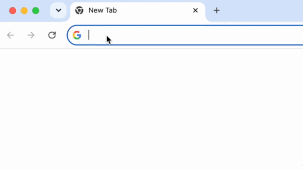
Step 1: Open Google Search and head to Settings
Head on over to Google.com in your browser.
Then look for Settings at the bottom right of the page. Click it, then select Search settings from the popup menu.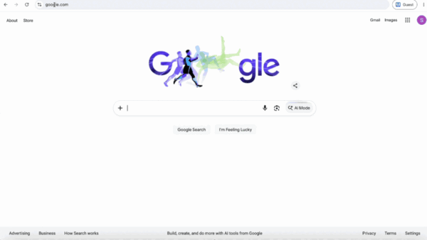
Step 2: Find the "Search Personalization" section
Once you're in Search Settings, scroll down until you spot the Search Personalization section.
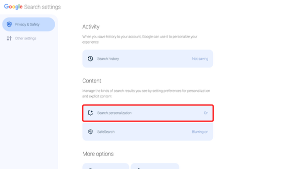
Step 3: Click on the Source Preferences button,
Now that you're in the Search personalization menu, scroll down until you see Source preferences and click on it. This will bring you to the Source preferences page.
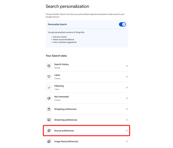
Step 4: Add AlarmGrid as a preferred source
Click Add a source, then type in: alarmgrid.com
Click the checkbox next to alarmgrid.com to set it as a preferred source.
That's it. You just told Google, "Hey, I trust these people," and now when you Google search with a relevant question Alarm Grid will be prioritized.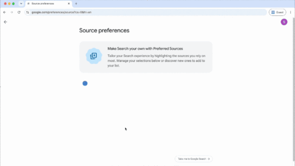
That's all there is to it.
From here on out, when you search for anything security related: panel setup, sensor troubleshooting, z-wave devices, you name it, AlarmGrid results jump to the front of the line. No more TechDad47, no offense to him. Just real answers from people who actually know their way around a security system.
A couple of things worth knowing:
- This setting is tied to your Google account, so it follows you across devices as long as you're signed in.
- Google can still show results from other sites. This just moves AlarmGrid to the top of related results.
- You can add up to three preferred sources total, so choose wisely. We're not saying pick us three times, but we're not not saying it.
Why AlarmGrid?
We've been writing detailed, no-fluff guides on home security systems for years. Our content is written by people who actually use and test this equipment, not scraped, not outsourced, not phoned in. If you want to browse what we've got, head to alarmgrid.com. There's a good chance we've already answered whatever you're about to Google.
If you need help or have questions about anything Alarm related, our support team is here Monday - Friday from 9:00 AM - 8:00 PM Eastern. You can contact us at 888-818-7728 or by emailing support@alarmgrid.com.


