Alarm Grid is thrilled to inform you that the new 2GIG 345S encryption-capable sensor lineup is now available. This collection covers all the bases, with sensors for security, life safety, and environmental monitoring. The 345s sensors allow you to select encrypted or non-encrypted operation.
If you're building out a new 2GIG system or expanding an existing one, you are going to want to take a close look at what this family of products has to offer.
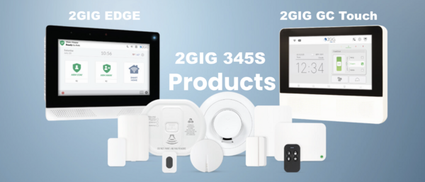
All of the 345S sensors communicate on the standard 345 MHz wireless frequency. That means they play nice with a wide range of 2GIG panels, including the 2GIG GC Touch (AT&T LTE and Verizon LTE versions), 2GIG GC2e, 2GIG GC3e, and Edge (AT&T LTE and Verizon LTE versions available). They will also work right alongside any existing 2GIG or Honeywell 5800 Series sensors you already have enrolled.
And here is a nice bonus: the sensors in this lineup come with an onboard encryption switch, so you can enable encrypted communication if your panel supports it. They come from the factory with encryption disabled, but enabling it is super easy.
With that said, let's check out the new 345S sensors!
345S Wireless Door/Window Contact Sensor

The 2GIG DW100-345 is a surface-mounted door and window contact that should be one of the first sensors on your shopping list. It mounts right onto the surface of a door or window frame and communicates wirelessly with your panel whenever the magnet separates from the sensor, letting the system know something has been opened.
One thing we really like about this one is the thoughtful design. It has a rounded outer shell with a square interior, which makes it easy for installers to line up correctly during mounting. It also ships with a spacer that lets it fit flush on a wider variety of door and window profiles. You get support for an external Normally Open or Normally Closed wired input as well, which gives you some extra flexibility. Battery life comes in at up to 8 years, and encryption is switchable on or off right on the board.
Key Features:
- Surface-mounted design with included spacer for versatile installation
- Up to 8-year battery life
- Supports external NO or NC wired input
- On/Off switchable encryption via onboard switch
2GIG DWR100-345
345S Recessed Door/Window Contact Sensor
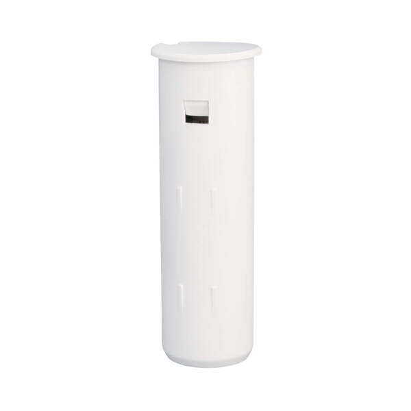
If you want your security sensors to be completely out of sight, the 2GIG DWR100-345 is the way to go. This is a recessed contact, which means the sensor and its magnet get installed inside holes drilled into the door or window and its frame. Once everything is in place, the only way you would ever notice the sensor is by looking at the edge of the frame with the door or window already open.
This is a fantastic option for anyone who cares about keeping their home looking clean and uncluttered. It communicates on the 345 MHz frequency and will report to the panel whenever the door or window is opened. Battery life is rated at up to 5 years, and encryption can be toggled on or off using a switch right on the sensor.
Key Features:
- Completely hidden recessed design for a clean look
- Up to 5-year battery life
- On/Off switchable encryption via onboard switch
345S Passive Infrared Motion Detector

The 2GIG PIR100-345 is a wall-mounted motion detector that uses passive infrared technology to pick up on changes in heat energy caused by movement. When set to its default High Sensitivity Mode, it covers an impressive area of 30 feet deep by 50 feet wide. That is more than enough for a typical living room, hallway, or open floor plan.
Pet owners will appreciate the built-in pet immunity feature. When enabled, the sensor will ignore the movement of animals weighing up to 85 pounds, which goes a long way toward cutting down on false alarms. The sensitivity setting is installer-adjustable, so you can dial it in for your specific environment. Battery life is rated at up to 7 years, and like most sensors in the 345S lineup, encryption can be toggled on via an onboard switch.
Key Features:
- 30 ft x 50 ft coverage area on high sensitivity
- Pet immunity for animals up to 85 lbs (installer-adjustable)
- Up to 7-year battery life
- Ships non-encrypted; encryption activated via onboard switch
345S Wireless Glass Break Detector
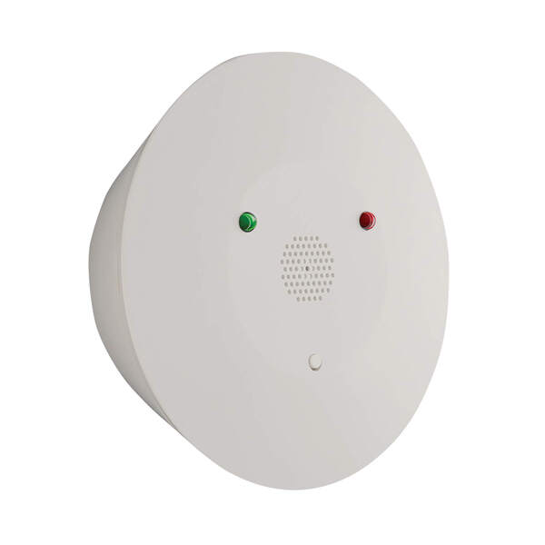
The 2GIG GB100-345 is a wireless glass break detector that can be mounted on either a ceiling or a wall. It uses a dual-stage detection method to tell the difference between actual breaking glass and other loud noises. First, it listens for the low-frequency "thud" of something striking the glass. Then it listens for the high-frequency "crash" of the glass actually shattering. Both sounds have to occur together for the sensor to trip, which does a great job of preventing false alarms.
It handles plate, tempered, laminated, and coated glass, and it covers a 15-foot radius from where it is mounted. There are user-adjustable sensitivity settings as well, which is helpful if the sensor is going in a noisier area. Battery life is up to 5 years, and encryption is switchable on the board.
Key Features:
- Dual-stage thud and crash detection to minimize false alarms
- Detects plate, tempered, laminated, and coated glass
- 15-foot detection radius
- User-adjustable sensitivity settings
- Up to 5-year battery life
- On/Off switchable encryption
345S Smoke, Heat, Freeze Detector
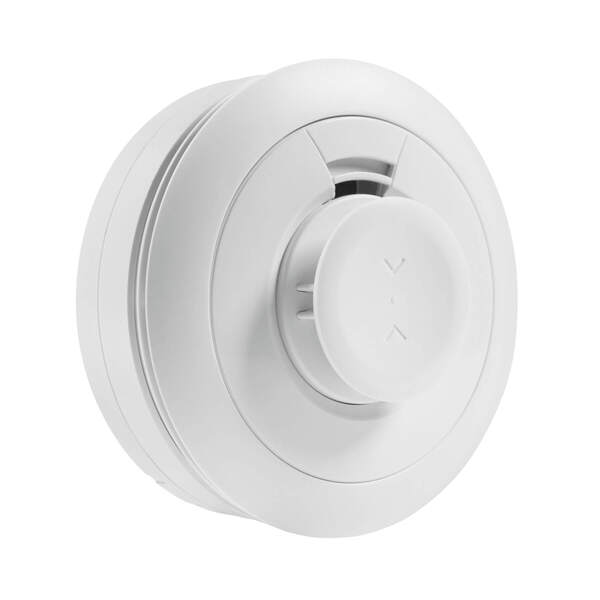
The 2GIG SMKT100-345 is a multi-purpose life safety sensor that handles smoke, heat, and freeze detection all in one device. It uses a photo-electric optical smoke detection chamber paired with advanced detection algorithms, and it meets the newer UL217 8th edition and UL268 7th edition standards. That means it is better at recognizing smoke from synthetic materials, which is important since so much of what is in our homes today is made from plastics and other synthetics.
Beyond smoke, the sensor also monitors for dangerous temperature conditions. It sends a Rate of Rise alert when the room temperature hits 104 degrees Fahrenheit and climbs 15 or more degrees within a single minute. It will also alert you to extreme high and low temperatures, making it useful as a freeze sensor for vacation homes or unoccupied spaces. The projected battery life is 10 years, and encryption is enabled by default on this one, though it can be switched off if needed.
Key Features:
- Meets UL217 8th edition and UL268 7th edition standards
- Photo-electric optical smoke detection chamber
- Rate of Rise heat alert (104°F + 15° rise in one minute)
- Extreme high and low temperature freeze alerts
- Projected 10-year battery life
- Default encrypted; can be switched to unencrypted mode
2GIG CO100-345
345S Carbon Monoxide Detector
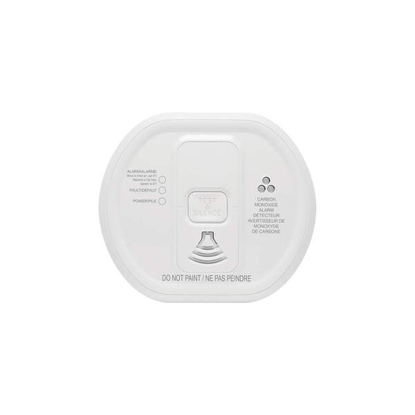
Carbon monoxide is one of those dangers you absolutely cannot detect on your own, which is why the 2GIG CO100-345 is such an important addition to any system. This wireless CO detector uses an electrochemical sensor to monitor for carbon monoxide and communicates alarm, tamper, and battery condition messages back to your panel.
What really stands out here is the longevity. You get a 10-year sensor life and a 10-year battery life, so once this thing is installed, you can largely set it and forget it. It also has a built-in 85 decibel sounder to wake you up if CO is detected, even before the panel sounds its own alarm. The case is tamper protected and the sensor includes an end-of-life indicator so you know when it is time for a replacement. It is ETL listed for added peace of mind.
Key Features:
- 10-year sensor life and 10-year battery life
- Built-in 85 dB sounder for immediate local alerts
- Tamper protected case with end-of-life indicator
- Full monitoring of alarm, low battery, and tamper conditions
- ETL listed
345S Firefighter Smoke and CO Detector Listener
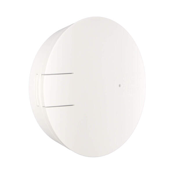
The 2GIG FF100-345 is a clever solution for a common problem. If you already have UL listed smoke or CO detectors in your home, you probably do not want to rip them out just to add monitoring to your security system. The FireFighter solves this by listening for the specific alarm cadence of your existing detectors and then relaying that signal wirelessly to your 2GIG panel.
The best part is that adding a FireFighter does not impact the UL listing or Fire Marshall approval of your existing detectors. It simply sits nearby and listens. It runs on a single CR123A long life lithium battery and is FCC, IC, and ETL listed for use in both the US and Canada. Encryption can be enabled via an onboard switch.
Key Features:
- Monitors existing UL listed smoke, CO, or combo detectors
- Does not affect UL or Fire Marshall approval of existing detectors
- Runs on one CR123A long life lithium battery
- FCC, IC, and ETL listed (US and Canada, UL985)
- On/Off switchable encryption via onboard switch
345S Wireless Dual Flood Water and Temperature Sensor

Water damage is one of the most expensive problems a homeowner can face, and the 2GIG FTD100-345 is designed to catch it early. This dual-purpose sensor monitors for the presence of water and also keeps tabs on the ambient temperature in its location. Place it near a water heater, under a sink, in a basement, or anywhere else where a leak or a burst pipe could cause serious damage.
It is part of the 2GIG Notification Sensors line, which adds smart home awareness features to your security system beyond just intrusion detection. The sensor runs on a single CR 2.3V lithium battery with a five-year battery life. Encryption can be enabled via the onboard switch.
Key Features:
- Dual flood and temperature monitoring in one device
- Runs on one CR 2.3V lithium battery
- Five-year battery life
- On/Off switchable encryption via onboard switch
345S Wireless Flood/Temp Sensor

The 2GIG FT100-345 is another option for flood and temperature monitoring. Like the FTD100 above, it can detect the presence of water and monitor for temperature changes that fall outside of defined thresholds. It is fully supervised and tamper protected, so you will know right away if anything goes wrong with the sensor itself.
This is a great sensor to place in utility rooms, crawl spaces, or anywhere you want early warning about water intrusion or freezing temperatures. It runs on a CR123A lithium battery with a five-year lifespan, and encryption can be toggled on or off at the sensor.
Key Features:
- Flood detection and ambient temperature monitoring
- Fully supervised and tamper protected
- Runs on one CR 2.3V lithium battery with 5-year life
- On/Off switchable encryption via onboard switch
2GIG TILT100-345
345S Wireless Tilt Sensor

The 2GIG TILT100-345 is a simple but really useful sensor. It monitors whether something has been tilted past a 45-degree angle, which makes it perfect for keeping track of your garage door status. Mount it on the inside of the garage door panel, and it will report to the system whenever the door goes up or comes back down. It sends a restore signal once the door returns to its closed position.
Beyond garage doors, you can also use it to monitor mailboxes, pet doors, storm cellar doors, or anything else that tilts when opened. It includes a tamper switch and low battery reporting. Installation is easy with the included double-sided tape and mounting screws. Battery life is rated at up to 10 years, and encryption is switchable on the board.
Key Features:
- Triggers at 45-degree tilt, restores when returned to upright position
- Perfect for garage doors, mailboxes, pet doors, and more
- Up to 10-year battery life
- Includes double-sided tape and mounting screws
- Tamper switch and low battery supervision
- On/Off switchable encryption
2GIG KEY100-345
345S 4-Button Security Panel Key Ring Remote
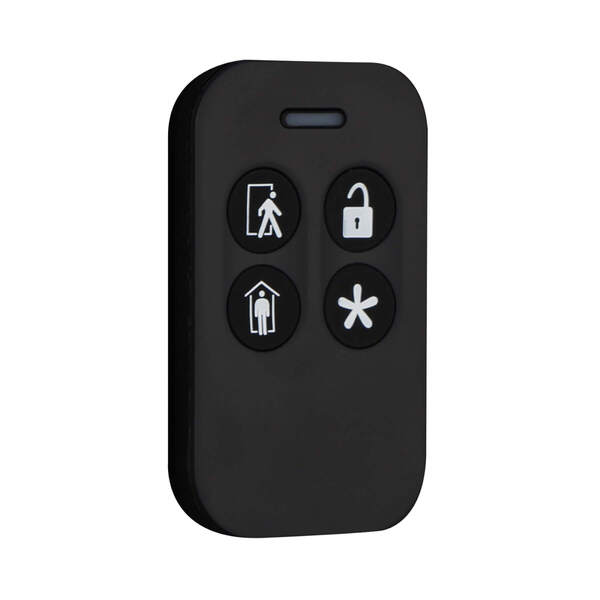
The 2GIG KEY100-345 is a wireless key fob that gives you a quick and convenient way to control your system without having to walk over to the panel. It has four buttons that let you arm, disarm, and trigger a panic right from your keychain, pocket, or purse. It supports encryption, which is highly recommended for a key fob.
If there is an emergency, you can hit the panic button to activate the siren and automatically signal the central monitoring station, if enabled. The key fob can also be programmed to operate the programmable output on the alarm panel, which is handy if you have a connected device like a garage door or gate relay. It is small, lightweight, and easy to keep on you at all times.
Key Features:
- 4-button control: Arm Away, Arm Stay, Disarm, and programmable output
- Emergency panic button activates siren and signals monitoring station
- Compact design fits on a key chain, in a pocket, or purse
- Programmable output control for connected relay devices
2GIG PANIC100-345
345S Wireless Panic Button Pendant Remote
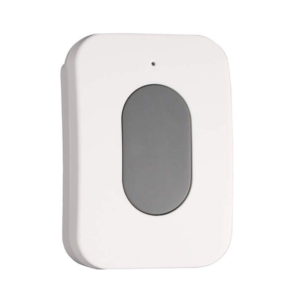
The 2GIG PANIC100-345 is a dedicated panic button designed for one thing: getting you help fast. Press the button and it immediately sends an emergency signal to the control panel, regardless of whether the system is armed or disarmed. It has a wireless range of 500 feet in open air, so it works from just about anywhere on your property.
What makes this device especially useful is how many ways you can carry or mount it. It comes with options for a lanyard, wristband, belt clip, and car visor clip. The button is water-resistant, which means it can get wet, but should not be submerged. That means it holds up well even in damp environments like bathrooms or near pools. A five-second lockout after each press prevents accidental reactivations, which is a nice safety touch.
Key Features:
- 500 ft wireless range in open air
- Water-resistant design
- Wearable via lanyard, wristband, belt clip, or car visor clip
- Five-second lockout prevents accidental activations
- Over 1 million unique ID code combinations
- FCC/IC and ETL certified
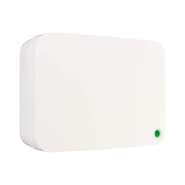
345S Wireless Hardwire Takeover Module

Upgrading to a 2GIG wireless system but your home is already wired up with hardwired sensors? The 2GIG TAKE100-345 is exactly what you need. This takeover module lets you convert up to 8 existing hardwired zones into wireless zones that communicate with your 2GIG panel. If you have more than 8 zones, you can add additional modules.
It supports up to 500 mA for powering wired motion sensors and glass break sensors, and it can even be powered by the backup battery of your old alarm panel. It includes a charging circuit with LED status lighting for the backup battery. Just keep in mind that it is intended for indoor use only and cannot be used for Carbon Monoxide or Fire detection zones. Encryption is supported via an onboard switch, and the module is ETL listed.
Key Features:
- Converts up to 8 hardwired zones per module into wireless zones
- Supports up to 500 mA for wired motions and glass breaks
- Can run on existing alarm panel backup battery with charging circuit
- LED status lighting for battery condition
- ETL listed
- Supports encryption via onboard switch
345S Wireless Repeater
If you have a larger home or a tricky layout with lots of walls and obstacles, the 2GIG RPTR100-345 Wireless Repeater can be a lifesaver. It extends the wireless range of your 2GIG system by receiving signals from your sensors and repeating them to the panel. It handles both 2GIG and Honeywell 5800 Series signals, and it works with encrypted and non-encrypted sensors right out of the box.
Setup could not be easier. It is a plug-and-play device that starts repeating signals the moment you power it on. It also includes a 24-hour rechargeable backup battery, so it keeps working even during a power outage. A built-in repeat indicator in the signal prevents the "repeated signal storm" issue that some older repeaters can cause. You can optionally program it as a zone to supervise Tamper, AC Loss, and Low Battery conditions for the repeater.
Key Features:
- Repeats both 2GIG and Honeywell 5800 345 MHz signals
- Works with encrypted and non-encrypted sensors out of the box
- Plug-and-play with immediate signal repetition
- 24-hour rechargeable backup battery
- Built-in repeat indicator eliminates repeated signal storm
- On/Off switchable supervisory encryption
Questions? We Are Here to Help!
If you have questions about any of these 2GIG 345S Sensors or 2GIG panels, or if you just want to learn more about our monitoring service, please reach out to us! The best way to contact us is to email support@alarmgrid.com. If you want to speak by phone, you can reach us at (888) 818-7728 during our regular business hours of 9am to 8pm Eastern Time. Visit our website to chat with a live agent between 9:00 AM and 6:00 PM Eastern.