DIY Security Systems Posts

Posted By

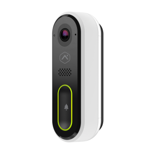
This week, Alarm.com offers some news. They have a firmware update for the Alarm.com Slim Line II Doorbells. It will be pushed automatically in the coming weeks. They're ready to support the new Qolsys panels. Also, a new MicroSD card will soon be available, made specifically for video devices.

The Alarm.com Slimline II Doorbells that are online and attached to Alarm.com accounts will be receiving a firmware update in the coming weeks. This update will be performed automatically, no input from the customer or the dealer is required. This update, Version 4089, will add compatibility for different internal components. Customers should not notice any change in performance regarding this update.

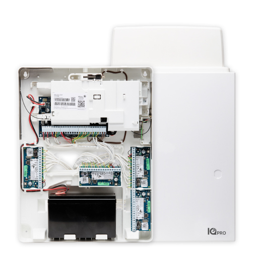
Alarm.com is ready to support the all new Qolsys IQ Panel 4. Currently, only the PowerG and 319.5 MHz versions of this panel (with either an AT&T LTE or Verizon LTE communicator) is available. However, additional versions of these panels, which will support Honeywell and 2GIG 345 MHz wireless in addition to PowerG in an AT&T LTE or Verizon LTE version, and then later DSC 433 MHz in addition to PowerG in an AT&T LTE or Verizon LTE version, will soon be available. We currently show the panels that are not available as being discontinued, but that will change as soon as stock becomes available. Bookmark the page for your panel, and keep checking back.

Alarm.com is ready for another new Qolsys panel, the IQ Hub. Now, they just need to get some available stock for this panel. The IQ Hub has a lot of the same features as the Qolsys IQ Panel 2, but each version of the Hub will only support one RF frequency. There will be a PowerG version, a 345 MHz version for those who will be replacing a Honeywell or 2GIG wireless panel, a 319.5 MHz version for those upgrading an older Qolsys or Interlogix panel, and a 433 MHz version for users who are replacing an older DSC panel, with an AT&T LTE or Verizon LTE version available for each of these "flavors".

Our final bit of news for the week is regarding Alarm.com cameras that support MicroSD cards. Alarm.com was offering a Micron i300 Industrial Memory Card (256 GB capacity) for use with their cameras that support local recording. They have switched to the WD Purple MicroSD Card (SKU: ADC-USD-256GB-WD). This card is less expensive, and with its high-endurance performance is designed for the 24/7 nature of use with surveillance cameras, particularly the Alarm.com cameras that offer Onboard Recording with the Smart View feature. Alarm Grid will soon begin offering this new and improved MicroSD card.

Tags: , , , , , ,

Comments


Posted By

Qolsys TSB #211022 indicates that the Qolsys IQ Panel 2 Plus, PowerG and 319.5 MHz version with any communicator has been discontinued. All kits containing these versions have also been discontinued. The IQ Panel 4 PowerG and 319.5 MHz panel is the appropriate replacement in this instance.

Currently Alarm Grid offers the Qolsys IQ Panel 4 Verizon LTE, Interlogix/GE Compatible 319.5 MHz Wireless Alarm Panel w/ PowerG, and the Qolsys IQ Panel 4 AT&T LTE, Interlogix/GE Compatible 319.5 MHz Wireless Alarm Panel w/ PowerG. Both versions will eventually be offered in Black or White color variations, but at this time only the White variation is available.

This announcement is only for the Interlogix/GE compatible panels that support legacy RF in the 319.5 MHz frequency. The other variations of the IQ Panel 2 Plus, those that support 345 MHz Honeywell and 2GIG legacy RF, and 433 MHz DSC legacy RF sensors are still available at this time. This is because production for the IQ Panel 4 versions of these panels has not yet begun.

Per Qolsys, the IQ Panel 4 PowerG and Honeywell/2GIG compatible panels that support 345 MHz legacy RF sensors are beginning production this week. As supply ramps up, the Qolsys IQ Panel 2 Plus that supports this legacy RF frequency will be phased out. We expect this to begin happening in the near future. Production of the IQ Panel 4 for the DSC compatible panels that support 433 MHz legacy RF sensors will begin production in early December, with a similar phase out of those IQ Panel 2 Plus models soon to follow.

As with the IQ Panel 2 Plus, each Qolsys IQ Panel 4 will support PowerG in addition to one (1) legacy RF frequency. In addition to choosing a panel based on the RF frequency to be used, the user will also want to choose the panel with the built-in cellular communicator that will have the best signal strength and quality in the location where the panel will be installed. This can match the carrier for the user's cell phone, but that is not a requirement. When deciding which cellular carrier to choose, base the decision solely on cellular coverage. Billing for the panel's cellular communicator will be included in the monthly monitoring service charges.

The legacy RF frequency built-in to the IQ Panel 4 is intended to make it easy to replace an existing alarm panel from a different manufacturer. By choosing the IQ Panel 4 that supports the wireless frequency for sensors that are already installed in a location, a user can save a lot of money by not having to buy all new sensors. You get the benefit of an all new, feature-rich alarm panel without the expense, not to mention the time and trouble saved, of replacing existing sensors that still work.

Were you thinking of purchasing a Qolsys IQ Panel 2 Plus in the 319.5 MHz "flavor"? If you were, you can purchase the IQ Panel 4 instead. This panel currently has the exact same User Interface (UI) as the IQ Panel 2 Plus, so the user experience will not differ. We expect the IQ Panel 4 to get a facelift in the near future, with the end-user having the choice of whether they want to use the new interface, or stick with the legacy one. The new UI is supposed to be very similar to the Alarm.com layout. If you have any comments, please leave them below. As always, we look forward to hearing from you!

Tags: , , , , , , , , , , , , , , , , , , , , , , , , , ,

Comments


Posted By

Alarm.com announced on Friday, October 22, 2021 that they plan to discontinue sales of the Concord 4 Dual-Path VoLTE Module and Gateway at the end of October. Interlogix, which is now owned by UTC (United Technologies Corporation) stopped making the Concord 4 panel in late 2019.

There were two (2) VoLTE Dual-Path communicators formerly offered by Alarm.com. The Alarm.com CD-411-US-AT AT&T LTE version, and the Alarm.com CD-421-US-VZ Verizon LTE version. Both of these modules have been on backorder for some time during the global chip shortage, which may have played a part in the decision to discontinue them.

As of now, there is still a Verizon LTE cellular-only communicator available for the Concord 4 panel. The Interlogix GE 600-1053-LTE-VZ connects to the Verizon LTE network for fast and reliable delivery of alarm signals and Alarm.com notifications. With Alarm.com service, the user also has the ability to review status and send alarm system commands remotely using the Alarm.com app or website.

UPDATE 10/26/21! We've discovered that the Interlogix GE 600-1053-LTE-VZ is not available from any of our vendors. We haven't seen an official discontinuation notice, but it seems it may have been. This means that currently, we can't offer any new LTE communicators for the Interlogix/GE Concord 4. For alarm reporting only, the Resideo LTEM-PA or LTEM-PV with the Resideo PRODCM Dialer Capture Module can be used.

The Concord 4 panel is not one that Alarm Grid sells. However, for those users with a Concord 4 in the field that is still working just fine, an updated communicator allows them to continue using a system they're comfortable with, while taking advantage of newly introduced features.

With a subscription to Alarm.com and one of the Verizon LTE communicators, not only can the user view the status of their system, arm and disarm remotely, and receive text, email, or push notifications on alarm events, but they can also add the convenience of Z-Wave functionality to the system. Z-Wave is a communications protocol that allows various devices in your home or business to communicate with the main system to do things such as turn on lights, set the thermostat to a particular temperature based on a Geo-Fence or on the armed status of the panel, and many more options. The Concord 4 panel just needs to be on version 4.0 or higher to support the use of the 600-1053-LTE-VZ communicator.

What do you think about Alarm.com discontinuing these modules? It's only been about a year since they were introduced. Do you think the global chip shortage led to the demise of the Concord 4 Dual-Path communicators? Leave a comment below and we can discuss further. As always, we look forward to hearing from you.

Tags: , , , , , , , , , , ,

Comments


Posted By

Resideo and Honeywell Home have just released Firmware Version 03.592.107.0 for the PROA7 and PROA7PLUS panels. This update allows the PROTAKEOVER module to support 5800 Series life-safety sensors like the 5808W3, 5800CO, and more. In addition, it offers some other features and improvements.

There are four (4) different panels in the Resideo and Honeywell Home ProSeries lineup. The Honeywell Home PROA7, and Honeywell Home PROA7PLUS, and the Resideo PROA7C and Resideo PROA7PLUSC. The 03.592.107.0 Firmware Version applies to all of them. The differences between the Resideo versions and the Honeywell Home versions are purely cosmetic. You can find details about that in a previous post.

The biggest news in this firmware release is the addition of life-safety support when using the PROTAKEOVER module. For the Honeywell 5800 Series legacy RF sensors, the use of life-safety sensors such as the 5808W3, 5806W3, 5800CO, and others has actually been ETL tested and passed to the UL Residential Fire standard. When taking over a CO detector, be sure to check the expiration date. CO detectors are usually good anywhere from six (6) to ten (10) years. Life-safety sensors from any of the other manufacturers supported by the PROTAKEOVER, including DSC (433 MHz), Bosch (433 MHz), 2GIG (345 MHz), Qolsys, and Interlogix (319.5 MHz), can be used, but they will not meet the ETL listing requirement.

When life-safety devices are used with the PROTAKEOVER the functionality for Loop 2 becomes automatic. For sensors programmed for Fire, Loop 2 automatically becomes the Maintenance (Clean Me) input. For those programmed as Carbon Monoxide, Loop 2 automatically becomes the End-of-Life input. For this reason, if you use a 5817CB or 5817CBXT, for something such as a wired heat detector input, you MUST strap out the loop 2 input, either with a wire jumper or a resistor, depending on which 5817 you're using, and you cannot use that input for a zone on the system.

Although the addition of life-safety support for legacy RF sensors is the big news in this firmware release, it is by no means the only news. This revision adds the ability to enable or disable on-screen panic alarms. It also adds the ability to program scenes via Total Connect 2.0 that pertain to alarm panel arming and disarming events only. Even if the panel itself doesn't have a PROWIFIZW module installed (Smart Home monitoring plan is still required). Prior to this release, if you had no intention of using Z-Wave devices, but you still wanted to program your system to arm or disarm based on a schedule, you couldn't do so unless you installed a Z-Wave controller in the panel.

Below, we'll list all the added or updated features with an explanation of each:

  • Zone Response Type Enhancement: The Device Type "Other" now offers the option to enable Chime. The PROSIXC2W now supports 24-Hour panic response types including 24-hour Silent, 24-Hour Audible, 24-Hour Medical, & 24-Hour Auxiliary. All Device and Response Types are now available when enrolling wireless zones using the PROTAKEOVER module.
  • LCD Keypad (PROSIXLCDKP) Enhancement: Now, when a Duress Code is entered at the wireless LCD keypad, only the 4-digit code is required. Previously, users would have to enter the 4-digit code + OFF [1].
  • Quiet Time Feature Added: The PROWLTOUCH Keypad now participates in Quiet Time (10:00 pm - 8:00 am). This means that non-emergency Trouble conditions, and Low Battery troubles will not sound the keypad during this time, though they will display. Included in this list are Communicator Trouble, System Low Battery, RF Transmitter Low Battery, RF Jam Trouble, AC Loss, and PROWLTOUCH Supervision Trouble. Sensor Tamper, and RF Supervision will sound. At 8:00 am, if the non-emergency trouble condition still exists, it will sound. This feature is automatic. It cannot be disabled, and the times cannot currently be changed, though that may change in future revisions.
  • Additional PROWLTOUCH Enhancements: While in backlight timeout, if the keypad reconnects to WIFI for any reason, the keypad will not illuminate. Keypad supervision is now defaulted as "Disabled". If a system has PROWLTOUCH keypad supervision enabled, updating to this version will NOT disable it. The Wireless Touchscreen keypad can now only be enrolled when the main panel is not in program mode. This prevents conflicts with the PROSIXLCD which MUST be added through panel programming. An issue has been corrected where, if the keypad locked up, the battery had to be removed and re-installed in order to reset the keypad. The Indoor MotionViewer (PROINDMV) clips can now be played back on the PROWLTOUCH as well as on the main panel.
  • End-user Can Push User Codes to Z-Wave Locks From TC2: Whew, that was a mouthful! Any Total Connect 2.0 Admin user can now create a user code and send it to a Z-Wave lock via either the Mobile App, or the Website. They have the option to both Push the User to the Lock, and allow the Lock Disarm by that User to automatically Disarm the system.

  • Improved TC2 Behavior During a Z-Wave Lock Jam: Previously, when a lock jam condition was displayed, the only option available was to physically go to the lock and toggle the lock position. Total Connect 2.0 now gives you the option to attempt to Lock or Unlock through the app or website.
  • Z-Wave Lock User Code Sync Improvement: In the past, setting the panel user code to match the Yale lock user code would cause issues. This is still not recommended, but the behavior should be improved.
  • Security Scenes Available in TC2 Without PROWIFIZW: There is no longer a hardware requirement that the panel have the Z-Wave Controller installed in order to create TC2 Scenes pertaining to security panel-only scenes. Currently, the security system scheduling is only available for Partition 1, and a plan that includes automation (Smart Home) is still required.
  • Improved Skybell and TC2 Syncing: Some doorbell cameras were having issues syncing with TC2 after the previous firmware update. Those issues should be resolved.
  • Improved PROSIX RF Signal Level Indication: The system now refreshes signal level for PROSIX devices immediately upon entering walk-test mode.
  • Improved TC2 Camera List Sync: In the past, it was sometimes necessary to Sync the panel twice to get an accurate camera list. This has been improved.
  • Partition Master User Enhancements: A Partition Master User can now only see event logs for the partition(s) they are authorized for.
  • Language Corrections: Improvements in translations for both French and Spanish.
  • Cyber Security Updates: Ongoing Cyber Security maintenance, as well as other bug fixes.

This firmware update can currently only be installed via WIFI. Any account communicating via cellular only will need to be connected to a mobile hotspot or other "WIFI" option before it can be updated. The size of this update is approximately 8MB.

This is a huge update with a lot of feature additions and some user-recommended improvements. Leave a comment below and let us know what you think about the ProSeries panel and the 3.5 update. As always, we look forward to hearing from you!

Tags: , , , , , , , , , , , , , , , , , , , ,

Comments


Posted By

When it comes to alarm panels behaving as Z-Wave Controllers, it should be easy to determine if a device is compatible or not. However, we've found that in some cases, not all Z-Wave devices are equal. Z-Wave locks by Schlage have been known to have compatibility issues with certain panels.

Alarm Grid has often stated in our documentation that we prefer that our customers use the Yale or Kwikset Z-Wave locks. We've seen issues with Schlage locks over the years and we haven't really gotten satisfactory answers as to why. We've had customers tell us that they've worked with Schlage, and we have worked with Resideo and Honeywell Home. Sometimes they will work, but other times the customer winds up changing to a different lock manufacturer, or just not using the locks with their panel.

When you look at the most current Lyric Z-Wave Compatibility Chart, which is dated 05/19, and is an official document produced by Honeywell Home, it shows that Schlage Z-Wave locks are compatible. This information is based on engineering and quality assurance testing. But testing and daily use are two different things. Engineers can never think up every scenario to test, no matter how hard they may try. So, once a customer attempts to use the products together in their own home or business, some unforeseen factors may arise and cause issues.

We recently had a customer attempting to use a Schlage Z-Wave lock with a Lyric Security System. When the lock is paired with the panel, the batteries drain very quickly, within one to two weeks. When the lock is used as a stand-alone device, the batteries appear to have a normal life. So, we asked Resideo Technical Support for their input. They suggested that the Schlage locks not be used with the Lyric, ProSeries, or Tuxedo products at this time. There is some conflicting information, certain locks may work with the ProSeries panels while others do not, but it may be best to avoid Schlage locks with these panels for now unless you can wait to use the panel and lock together until the issues are resolved.

The Lynx Series panels appear to support the Schlage locks when the L5100-ZWAVE is employed, but certain conditions must be met. The lock and the panel must be within 12 inches of one another during the pairing process, and must remain at this distance for a full two (2) minutes before either is moved. This allows the full pairing process to be completed. Also, the handing process must be completed immediately following pairing. Resideo engineers are working with Schlage to resolve any issues with those panels that have them, and they hope to have a resolution some time soon, possibly in early 2022.

If you have any thoughts about Schlage Z-Wave locks and their use with any of the Resideo or Honeywell Home alarm systems, drop a comment in the area below and lets get a conversation started. We offer feedback directly to all our vendors on behalf of our customers. We're honored to be your voice.

Tags: , , , , , , , , , , , , ,

Comments


Posted By

Until now, only alarm systems manufactured by Resideo, Honeywell Home, or Honeywell could be used with Total Connect 2.0. That changes with the new LTEM-P Series communicators. Some DSC and Interlogix panels can now be connected to and used with TC2. A supplemental wiring guide is provided.

The LTEM-PA AT&T LTE Communicator, and the LTEM-PV Verizon LTE Communicator available from Resideo can be used to send alarm signals on behalf of all the same VISTA panels that were compatible with the older AlarmNet communicators such as the Honeywell LTE-IA, and the Honeywell LTE-IV. In addition, certain versions of some of these panels can also be used with Total Connect 2.0 Remote Services when one of these communicators is attached to it.

With the release of the LTEM-P Series communicators, DSC PC1616, DSC PC1832, and DSC PC1864 panels can support both reporting through the communicator when it is connected to the panel's keypad bus and integration with Total Connect 2.0. In addition, Interlogix NX8E, NX-4V2, NX-6V2, and NX-8V2 panels can also be used with the LTEM-P Series communicators to both send signals, and integrate with TC2.

With the DSC PC Series panels, this is purely a keypad bus connection. The communicator's RX, TX, and Ground terminals will connect to the DSC panel's Green, Yellow, and Black keypad bus terminals. On the Interlogix NX Series panels that are supported, there is a connection to RX on the communicator from the terminal marked DATA on the panel's keypad bus. COM from the NX Series panel will connect to GND on the Communicator. In addition to this, the LTEM-P Series communicator will require a Resideo PRODCM Dialer Capture Module, which will connect to the panel's Tip and Ring terminals. The PRODCM will be installed inside the communicator. Panel signals are sent via the PRODCM, and Data Bus information for Total Connect 2.0 is sent from the bus.

There are some programming options that will need to be configured properly, for example the NX panel must be set to report in Contact ID format. In fact, all signals for both panel types will be sent to the monitoring station using Contact ID. The wiring connections should be made while both the panel and communicator are powered down. The alarm panel is powered up first, and all troubles, faults, and alarms must be cleared. Once they are, power up the communicator and it should begin to scan the panel's bus for zone information. This process can take up to ten (10) minutes.

This is not meant to be a step-by-step guide to setting up this feature, it's just an introduction to the feature for those who may not be aware that it is available. We offer an FAQ for using the DSC panels with TC2 here. If you have one of the compatible DSC or Interlogix panels, and you are considering using it with one of the LTEM-P Series communicators, check out the Resideo LTEM-P Series Installation Guide, the Resideo Supplemental Install Guide for Non-VISTA panels, and for those using a compatible Interlogix NX-Series panel, also check out the Resideo PRODCM Install Guide. We have not yet had an opportunity to create our own in depth FAQs for this process on the Non-VISTA panels, but we will get to those in the near future.

Have any thoughts about Resideo and Honeywell Home finally embracing the use of their communicators with competitor's panels? They offered a dialer capture module in the past, but it installed outside the communicator and was somewhat unwieldy. Leave a comment below and tell us what you think. We always look forward to hearing from our readers!

Tags: , , , , , , , ,

Comments


Posted By

In recent years, consumers have seen more information about IP ratings. Probably the most common example is with regard to cell phones. First came the IP67 rating, and then IP68. Cameras, particularly ones for outdoor use, also have an IP Rating. IP Rating standards are controlled by the IEC.

The IEC is the International Electrotechnical Commission. They are the official body that defines the IP Code. The code is defined in IEC standard 60529. In europe, it is EN 60529. The purpose for the code is to provide specific information about ingress protection, as opposed to the use of terms like waterproof, or water resistant. One company's water resistant, may be another company's waterproof. The IP Code is intended to take the leeway out of these descriptions.

The digits in an IP rating indicate conformity to protection under certain conditions. When you see a 0 in an IP rating it means that no protection is provided for that particular portion of the code. An X means that there is not enough data to determine the amount of protection. IP ratings will never have a - in them, so a product claiming to have a rating of IPX-8 is providing invalid information.

There are four (4) digits possible in an IP Code. For our use, only the first two (2) digits, which are mandatory, will be covered. Digit 1 describes the level of protection that an enclosure provides against access to hazardous parts, and the ingress of solid foreign objects. Digit 2 indicates the level of protection that an enclosure provides against harmful ingress of water. It should be noted that the ratings for water ingress are not cumulative. This means that just because something has a Digit 2 rating of 7, doesn't mean that it also has the Digit 2 rating of 1 - 6. If a device has protection against multiple types of ingress, it will be indicated by multiple ratings separated by a slash, for example, IPX5/IPX6.

Digit 1: Protection Against Solid Objects/Particles

Digit Value Effective Against Description
X - X indicates there is not enough data available to specify a protection rating for this type of protection
0 - No protection against contact or ingress of solid foreign objects
1 >2" (50mm) Any large surface of the body, such as back of hand, but no protection against deliberate contact with a body part
2 >.49" (12.5mm) Fingers or similar objects
3 >0.098" (2.5mm) Protection against tools, thick wires, etc.
4 >0.039" (1mm) Protection against most wires, slender screws, large ants, etc.
5 Dust protection Ingress of dust is not entirely prevented, but must not enter in sufficient quantity to interfere with proper operation of equipment.
6 Dust tight Complete protection against dust ingress. A vacuum must be applied, with test duration of up to 8 hours depending on airflow.


Digit 2: Protection Against Liquid Ingress

Digit Value Protection Against Effective Against Details
X - - X means there is not enough data available to specify a protection rating
0 None - No protection against water ingress
1 Dripping Water Vertically falling drops shall have no harmful effect when mounted in an upright position on a turntable and rotated at 1 RPM Test duration: 10 minutes
Water equivalent to .039" (1mm) rainfall per minute
2 Dripping Water while tilted at 15° from normal position. Vertically dripping water shall cause no harm when the enclosure is tilted at 15°. Four (4) positions are tested on two (2) axes. Test duration: 2.5 minutes per direction (10 minutes total)
Water equivalent to .12" (3mm) rainfall per minute
3 Spraying water. Water falling as a spray at any angle up to 60° from vertical shall have no harmful effect. A) Test uses either an oscillating fixture or B) a spray nozzle with a counterbalanced shield.
Test A lasts for 5 minutes, then is repeated with the test object rotated 90° horizontally for another 5-minute test. Test B is conducted with the shield in place for no less than 5 minutes.
Test duration: For a spray nozzle, 1 minute per square meter for at least 5 minutes. Water Volume: 10 liters per minute (.037impgal/s) Pressure: 7.3-21.8 psi (50-150 kPa)
Test duration: Oscillating tube duration 10 minutes. Water volume: .00026 impgal/s (.07 liters per minute) per opening.
4 Splashing of water. Water splashing against the enclosure from any direction shall have no harmful effect.
Test Utilizes either A) An oscillation fixture or B) A spray nozzle with no shield. Test A is conducted for 10 minutes. Test B is conducted without shield for 5 minutes minimum.
Test duration: Oscillating tube duration 10 minutes. Spray nozzle is the same as #3 with the shield removed.
5 Water jets. Water projected by a nozzle .25in (6.3mm) against the enclosure from any direction shall have no harmful effect. Test duration: 1 minute per square meter for at least 3 minutes. Water volume: 12.5 liters per minute. Pressure: 4.4 psi (30kPa) at a distance of 9.8' (3m).
6 Powerful water jets. Water projected in powerful jets .49" (12.5mm) against the enclosure from any direction shall have no harmful effects. Test duration: 1 minute per square meter for at least 3 minutes. Water volume: .37 impgal/s (100 liters per minute). Pressure: 15 psi (100 kPa) at a distance of 9.8' (3m).
6K Powerful water jets with increased pressure. Water projected in powerful jets .25" (6.3mm) against the enclosure from any direction, under elevated pressure, shall have no harmful effects. This standard is found in DIN 40050, not IEC 60529. Test duration: At least 3 minutes. Water volume: .27 impgal/s (75 liters per minute). Pressure: 150 psi (1,000 kPa) at a distance of 9.8' (3m).
7 Immersion, up to 3'3" (1m) in depth. Water ingress in a harmful quantity shall not be possible when the enclosure is immersed in water under the defined conditions of pressure and time. Test duration: 30 minutes. Tested with the lowest point of the enclosure 39" (1,000mm) below the surface, or the highest point 5.9" (150mm) below the surface, whichever is deeper.
8 Immersion, 3'3" (1m) or more in depth. Suitable for continuous immersion in water under conditions specified by the manufacturer. For some equipment, it means water can enter, so long as it causes no harmful effects. The test depth and duration should exceed the requirement for IPX7, and other environmental effects may be added, such as temperature cycling before immersion. Test duration: Agreed upon by the manufacturer. Depth: Specified by the manufacturer, but generally up to 9.8' (3m).

There is a Digit 2 rating of 9K, but it is reserved for specialty equipment so most DIYers won't be concerned with it. For that reason, we have omitted it here. So, when you see a product that has an IP66 rating, now you'll know what that means. It means the product is dust tight, and can stand up to powerful water jets without harmful water ingress.

The information for the tables above came from various enclosure manufacturer sites all over the web. I would have liked to have gotten the information directly from the IEC itself, but to download a PDF of this standard you must pay a hefty fee. For that reason, we did not get this information from the horse's mouth, as they say, but we attempted to fact-check it to the best of our ability. Any mistakes are the author's alone.

So, what do you think about the IP ratings system? Are you ready to take your phone out and give it a test? Tell us your thoughts in the comments below. Did you find this information helpful? Is there other information you'd like to see covered? Leave a comment, or shoot an email to support@alarmgrid.com. We'll do our best to be accommodating. As always, stay safe!

Tags: , ,

Comments


Posted By

From the beginning, ever since place-based services have become a staple of alarm-based remote access, Alarm.com has provided a better experience than their closest competitor, Total Connect 2.0. Recently, they announced they will be rebranding, with a name change from Geo-Services to Places.

Geo-Services, soon to be re-christened Places, allows a user to create a geo-fence around any location, and then create rules for their panel and their other automation devices based on that geo-fence. For example, you could create a rule that tells the system when your iOS or Android device enters the geo-fence, turn on the porch light

Alarm.com users with Master Control, Full Control, and Custom with Notification Settings enabled can configure Places. The feature can be enabled from the customer app by selecting Menu > GeoServices > and setting the feature to enabled:


You'll be prompted to go to your devices Location Settings and choose to Allow Always in order for the Places feature to function correctly even when the Alarm.com app is not in use. Once the feature is enabled on one or more devices, you can then create a geo-fence. One of the changes that is coming in early November is the ability to manage geo-fences from the customer app. Previously, the ability to configure this option was only available through the Alarm.com website.

Since this change hasn't actually been implemented yet, there is a chance that the menu options mentioned and shown above may change. Geo-services is included in every Alarm.com plan, and there is no additional charge to enable it. Geo-services uses the phone and WIFI networks to determine the location of the geo-services enabled device, rather than the built-in GPS. This is because using actual GPS consumes a lot of battery, but for this reason, location accuracy suffers. It can be off by as much as 3km, although that's not something we've experienced personally. Also, there is a tiny amount of cellular data used when WIFI is not available. About 100 bytes of data or less per geo-fence crossed.


Available Rules and Reminders For Geo-Services

Feature Description
Arming/Lock/Sensor/Garage/Gate Reminders Used to alert a user if the alarm isn't armed when the geo-fence is crossed. Can be used for locks, sensors, and garage doors as well.
Thermostat Override Set a desired temperature when leaving and/or returning to a location when the geo-fence is crossed. Works with thermostats and mini-splits controllers.
Pause Video Recordings Allows user to configure video devices to automatically pause recordings triggered by motion detection based on whether one or more geo-devices are within a geo-fence. Used to avoid unnecessary or unwanted recordings.
Automate Light Rules A user can create an event-triggered rule to automate lights based on when a geo-fence is crossed.

This is just a brief overview of this excellent Alarm.com feature that you may have, but may not be using. Be on the lookout for some possible changes to this feature early next month. If there are substantial changes, we'll be sure to keep you in the loop! Leave a comment below and let us know your thoughts about this, or any other alarm features. We look forward to hearing from you.

Tags: , , , , ,

Comments


Posted By

One of the good things about an alarm system is the fact that there are redundancies built-in. This prevents a single point of failure. To be certain that everything is working as it should, proper testing is required. Life-safety devices should be functionally tested on a regular basis.

There are numerous aspects to an alarm, that's why it's called a system. The senors are its eyes and ears, the keypad and sirens are its mouth, the alarm panel is its brain, and the communicator is how it calls for help. Whether that's by an old-fashioned POTS line, or cellular, or IP. It is recommended that all the basic aspects of the system be tested once a month. That means putting the system on test with the monitoring station, if necessary, then setting off an alarm and making sure that it both shows up locally at the keypad, causes the siren to sound if applicable, and communicates successfully to the monitoring station.

When an alarm system is first installed, it should be tested in such a way that every single facet of the system is verified to be working properly. That means every zone should be tested, and verified to have performed as programmed, including sending a report to the monitoring station, if central station monitoring is in use. It is important to do this properly because it sets a starting point. When you know that everything was working on a particular date, then later tests may be spot tests, without having to test every single zone. If you keep good records, then if a problem does arise, you'll be able to look back and know when was the last time this particular portion of the system was known to be working, and begin troubleshooting from there.

Smoke detectors and carbon monoxide (CO) detectors are considered life-safety devices. They can be wired to the alarm system, but they are often battery powered and some may be wireless, but still connected to the alarm system. There may be others that are battery powered, stand-alone devices that only sound locally, and are not tied to the alarm system. When moving into a home where an alarm system is already installed, it's very important to determine what life-safety sensors are present, whether they are stand-alone or tied to the system, and if possible, get any testing records, and any information you can on battery maintenance. If there are no life-safety sensors, or if there are none that are tied into the system, make it a priority to change this as soon as you can. Always follow the recommended guidelines when laying out the life-safety portion of your system.

Smoke and CO detectors can be tested in two ways. Each device usually has a push-button on the device itself. Depending on the device, pressing this button will cause the detector to sound locally and test its own battery. With newer devices, testing one smoke or CO detector in this way will cause all of the associated life-safety devices on the system to sound. This is called one-go-all-go by some manufacturers. There is usually an LED that provides feedback with this test, with some detectors actually speaking their status. If this happens to be a life-safety sensor that is tied into an alarm system, then pressing the test button should also cause an alarm condition to show up on the system keypad, and if the system is being monitored by a central station, a signal will be sent. If a low battery condition exists, it should be displayed via LEDs, or spoken, on the detector itself, and will show up on the alarm keypad if the detector is tied to the alarm system.

The above test is fine for the monthly system test, but at least twice per year, life-safety devices should undergo a functional test. A functional test is where you actually cause a smoke or a CO alarm. With smoke detectors, you can sometimes do this by lighting a 3-wick candle then blowing it out right under the smoke detector. Functional testing of a CO detector is more difficult, but still possible. We offer both canned CO for testing, and canned smoke. When testing, it may be helpful to hold a bowl upside-down over the detector to be tested. Make the bowl only as large as is necessary to cover the detector completely. Spray the canned smoke or canned CO into the area covered by the bowl. This should result in an alarm with a minimum of the canned product being wasted. It will also prevent you from possibly breathing it in. It is recommended to perform the functional test during the Spring and Fall, at the same time that the clocks are changed for Daylight Saving's Time. This Fall, that's going to happen on November 7, 2021.

Once you've caused an alarm to occur either with actual smoke, or with canned smoke or canned carbon monoxide, you can perform a disarm at the panel keypad to silence the system. It is possible that the system will begin sounding again if there is still smoke in the sensing chamber of the smoke detector, or canned CO in the sensing chamber of the CO detector. To stop the alarm, you need to clear the chamber. That means removing the bowl or other covering you used during the functional test, and blowing out the chamber. Be careful not to breathe in the canned test product. It is noxious! It may be helpful to have a fan handy, or possibly some canned air but be careful not to damage the sensing chamber. If using canned air, hold it at a distance of eight (8) inches or more from the detector.

Testing CO detectors is particularly important at this time of year. Carbon Monoxide buildup is caused by the inefficient burning of certain types of fuel. Natural gas, oil, kerosene, gasoline, wood, and charcoal are all fuel sources that can cause CO poisoning when not burned efficiently. As we head into the colder months, the use of all of these types of fuel for heating and recreation will be on the rise. If you're interested in how carbon monoxide detectors work, you can learn more here.

Above is a general guideline for how to functionally test smoke detectors and CO detectors. Follow the instructions found with the product literature for proper testing and be sure, if your system is monitored by a central station, that you call and put the system on test with them prior to causing an alarm. There are a number of ways that you can accomplish this. You can call the monitoring station, provide verification of your identity, then ask the operator to put your system on test. If you are an Alarm Grid customer, you can use the myalarms.com feature to put your system on test and take it off. If you are an Alarm.com subscriber, you may be able to put your system on test, or take it off, through the Alarm.com app. Alarm Grid has many guides, both written and video, to various specific smoke detectors and CO detectors. Check out our Youtube channel, or search the site for information on your devices. If we don't have information on a device you need to test, if it's one we sell leave us a comment below and we'll be happy to create content for that specific device.

Tags: , , , , ,

Comments


Posted By

AlarmNet360 is both a website and an app that can be used to create, edit, and cancel AlarmNet accounts. Access to this website and app is only available for licensed alarm dealers who are affiliated with AlarmNet. As an end-user you will not need to have or create an AlarmNet360 account.

Being a DIYer in the alarm industry can be pretty confusing at times! Nearly all of the documentation provided with alarm systems that have historically been installed only by alarm professionals is intended only for alarm professionals. So, when you buy that new ProSeries or Lyric Alarm System, and you begin reading the installation instructions, one of the first things you are told to do is create an AlarmNet360 account. This is not something that you, as a DIYer will be able to do.

This is where Alarm Grid comes in. Alarm Grid is a DIY friendly company. We sell professional grade alarm systems to anyone who wants to buy them. Sometimes, alarm professionals purchase from us and then they go about configuring the system themselves because they have access to AlarmNet360. Sometimes, customers purchase from us and then hire their own alarm professional to install their system and that alarm professional completes the setup on AlarmNet360 themselves. But usually, when an individual buys a system from us, they then sign up for one of our no-contract monitoring plans, and then we set up their account through AlarmNet360.

The relationship between Alarm Grid and our monitoring customers is a symbiotic one. DIY alarm users choose not to pay a professional to do something that they can do themselves. That being the physical installation of the alarm equipment. With the proliferation of self-contained, all-in-one systems, installation has gotten more and more simple. A child can do it. We have several young customers in their teens who set up systems just because they enjoy doing it, and figuring out new and interesting ways to make things happen.

On the monitoring side of things, that's where restrictions start to come in. There are certain things that have not opened up to DIYers yet, and access to AlarmNet360 is one of those things. You may be thinking, "Forget AlarmNet360, what's AlarmNet?" You can read about AlarmNet here. At present, only alarm dealers can sign up for access to AlarmNet360 in order to be able to add, edit, or cancel AlarmNet accounts. Access to accounts is very tightly controlled. The only accounts that Alarm Grid can see in AlarmNet360 are accounts that are assigned to Alarm Grid, which usually means that Alarm Grid created them in the first place.

Alarm Grid chose the DIY business model in part because we have everything we need to administer accounts on the back end, but we don't have a team of installers to send out and put in systems. DIYers are our installers, and in turn we provide for them the account admin services that they are not allowed to perform for themselves. We sell reasonably priced, professional grade alarm equipment. The same equipment that just about any alarm dealer in the country will sell you, and we handle the administrative side of things, in addition to providing free, world-class technical support to our monitored customers. In exchange for that, we charge a reasonable monitoring fee with no activation fees, no cancellation fees, and no contracts. We also don't care if you buy your system from us or elsewhere. We will monitor any equipment that is within our power to monitor for the same prices we charge to monitor the equipment we sell.

So, when you crack open that new system, and start reading the instructions, skip the part where it talks about the AlarmNet360 account. Whoever you sign up for monitoring with will take care of that part. Do you have an AlarmNet communicator? Have you been stumped by the mention of AlarmNet360 in your system's documentation? Leave us a comment below and let us know if this information was helpful. We always look forward to hearing from you.

Tags: , , , , , , , , , , , , , , , , , , , , , , , ,

Comments