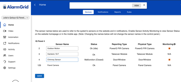
An Update to SkyBell "Gen5" Removes 3rd Party Access
Posted By Julia RossAnyone with a SkyBell Video Doorbell used with Total Connect 2.0 or Alarm.com, which is also used with the SkyBell app, be aware. The SkyBell app may prompt you to upgrade to "Gen5." However, upgrading will remove access from all third-party apps. Once installed, this upgrade can't be undone.
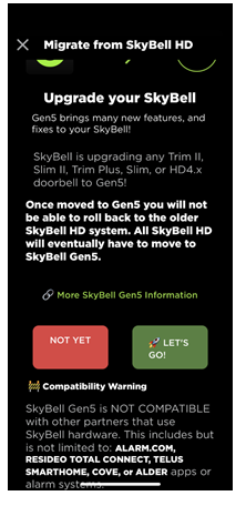
The message displayed in the SkyBell app is shown above. As you can see, any SkyBell Trim II, Slim II, Trim Plus, Slim, or HD4.x doorbell will eventually be upgraded to "Gen5," according to SkyBell. This means if you want to use a doorbell that is compatible with Total Connect 2.0 or Alarm.com, you will need to begin planning a video doorbell upgrade.
Currently, when prompted in the SkyBell HD App, you have the choice to select "Not Yet." However, this option will eventually be phased out, and the update will be automatically implemented. The exact timeline for this mandatory update is not yet known. This upgrade not only discontinues remote access via Total Connect 2.0 or Alarm.com but also eliminates compatibility with any local integrations involving Resideo touchscreen panels and keypads. We are still awaiting information regarding the impact of this change on alarm panels and keypads that utilize Alarm.com.
Alarm.com Update: According to Alarm.com CORE Technical Support, they are unaware of the Gen5 update, but since Alarm.com SkyBell doorbells use a proprietary version, and should never be connected to the SkyBell servers or app, this update should not affect their customers.
Alternative Video Doorbell for Total Connect 2.0 Users:
First Alert VX1 HD
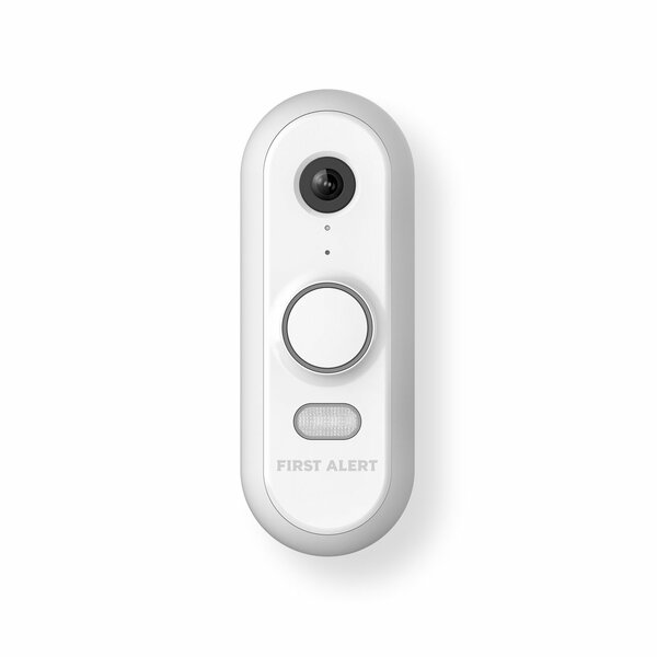
The First Alert VX1 HD is the first video doorbell offered by Resideo that is manufactured in-house. It is designed to replace an existing doorbell, so it does require power wiring. The VX1 HD offers dual-band WIFI connectivity using either 2.4 GHz or 5 GHz. Because of its advanced features, a Total Connect 2.0 plan that includes video monitoring is required to use this doorbell camera. For Alarm Grid customers this is either a Platinum Plan (Self or Full) or a Video Monitoring Plan. Each plan can support up to eight (8) cameras, and each VX1 HD counts as one (1) camera.
The VX1 HD is a 5MP camera, it supports 2-way audio and intelligent event detection. This is an advanced AI that can easily tell the difference between people, packages, vehicles, animals, and even loud sounds. This feature will limit unwanted recordings and accidental activations. There is a built-in LED and color night-vision options. It also has a built-in siren feature that can be manually activated to scare away unwanted visitors.
Another great feature of the VX1 HD is Wide Dynamic Range (WDR). We hear High Dynamic Range (HDR) mentioned a lot with Alarm.com cameras, but WDR is slightly different. With WDR, advanced software is combined with the ability to make hardware adjustments to provide the best image possible. Think of aperture iris adjustments and shutter speed control that allow the perfect amount of light to enter the recording. This is particularly important in images that combine very light and very dark areas. HDR also perfects images with high contrast, but it uses software only, without the ability to make hardware adjustments.
The VX1 HD supports three (3) unique options for its field of view. These are tall, wide, or full. Tall optimizes the camera for a portrait-style image, while Wide optimizes the camera for a landscape view. And finally, Full provides the largest possible visual area. There are also selections between low and high video quality. There are many other settings. You can adjust the use of the indoor chime, set how night vision works, and control the doorbell lights, the speaker volume, and the microphone volume.
The VX1 HD can use a mechanical or a digital chime and comes with an adapter for digital chime applications. It also comes with two (2) trim rings (white or grey), a straight and angled mounting bracket, a doorbell release/reset tool, and mounting hardware.
Alternative Video Doorbell Options for Alarm.com Users:
Alarm.com ADC-VDB770

When it comes to Alarm.com video cameras, we're spoiled for choice. The ADC-VDB770 is their flagship video doorbell and is the first manufactured specifically for Alarm.com. Like the VX1 HD, it supports dual-band WIFI (2.4 GHz and 5 GHz). It offers full HD recording with 1440 x 1920 video resolution. It boasts IR night vision with a viewing distance of up to 15' (4.5m). The viewing area is also impressive with a 150° vertical and 115° horizontal field of view.
The ADC-VDB770, like the VX1 HD, counts as a video camera when a video monitoring plan is used. If you have a single video doorbell camera, and no other video devices, you can add a single doorbell to an Alarm Grid Gold plan (Self or Full) without upgrading to a Platinum Plan. Just know, that if you already have a Platinum or Video Monitoring Plan, the ADC-VDB770 will count as one (1) when it comes to camera limits.
With High Dynamic Range (HDR), video recorded by the ADC-VDB770 is always crisp and clear. HDR is advanced software that optimizes each image so that it is as clear as possible. This is particularly important in images that have large areas of very light and very dark space. The ADC-VDB770 can work with mechanical or digital chimes. It is a wired doorbell camera and requires power. It should easily connect to an existing doorbell transformer rated between 16-30VAC and 10VA. Alternatively, a 15-30VDC, 8W minimum power adapter can be used. There is an included power module, and it is required in every installation, whether AC or DC power is being used.
The ADC-VDB770 also has an impressive list of available accessories, which you can purchase separately:
- ADC-VDBA-COVER - Touchless Doorbell Cover that lets guests know not to touch the video doorbell. Used in conjunction with the Video Doorbell Mat.
- ADC-VDBA-MAT - Video Doorbell Mat that lets guests know to activate the camera by standing on the mat. Used in conjunction with the Touchless Doorbell Cover.
- ADC-VDBA-PSU-PD - Video Doorbell Wall Power Supply Kit that is used if there is no existing chime circuit, or if the chime circuit is incompatible. Can be used with or without a power module. The device is rated at 16 Volts DC, 1.25 Amps, or 20 Watts.
- ADC-VDBA-TC - Temperature Collar Accessory that allows the doorbell camera to be safely used in temperatures as low as -40°F. Can be used with or without the Wall Mounting Plate.
- ADC-VDBA-WP - Wall Mounting Plate that hides blemishes such as missing paint or screw holes. Goes between the wall and the doorbell camera. Dimensions are 5.43"L by 3.43"W.
- ADC-VDBA-WMK - Wedge Mounting Kit that includes four (4) additional mounting bracket options that are not otherwise included with the ADC-VDB770. These mounting brackets are appropriately named D, E, F, and G. You will ultimately only use one (1) mounting bracket in the final installation.
Alarm.com ADC-VDB750

The ADC-VDB750 replaces the SkyBell ADC-VDB105X. It is a 2MP camera with a 165° horizontal and 145° vertical field of view. It's offered in three (3) colors, white, bronze, and silver. For most mechanical chimes, it doesn't require the installation of a power module, which simplifies installation.
Combined with the ADC-VDB750's excellent viewing area, this doorbell camera also offers 2-way audio, and video analytics for people detection. Unlike passive infrared (PIR) detection, which can be triggered by moving shrubs or holiday decorations video analytics uses software to determine whether an alert should be activated.
This video doorbell also offers an impressive operating temperature range of -58ºF up to 120ºF (-50°C - +48.8°C). It can be powered by an AC transformer rated at 16-24VAC, and 10-40VA or a DC power adapter with a rating of 15-24VDC, 6-20W. It does not have an internal battery. This allows it to be more versatile and compatible with a wider range of temperatures and hardware.
Unlike most video doorbells, the ADC-VDB750 has a programming option for no chime. For installations where no chime is being used, this doorbell camera does not require that a special resistor be installed. For a full list of features and specifications, please click the product link above to be taken to the product description page.
Alarm.com ADC-VDB780B
We'll round out our list of Alarm.com video doorbells with the ADC-VDB780B. This doorbell is unique among all those listed here because it is battery-operated and truly wireless. This doorbell is perfect for those who traditionally might not have a doorbell, such as apartment and condo dwellers, or those in older homes that don't have an existing doorbell, where a retrofit of a wired doorbell isn't possible or perhaps isn't wanted.
At Alarm Grid, we sell the VDB780B as a kit with an Alarm.com wireless chime. Each ADC-VDB780B must have at least one W115C to operate. The ADC-VDB780B-W115C-BNDL gives you everything you need to get a doorbell up and running in a location where no doorbell has ever been installed before. In addition to being a wireless chime, the W115C acts as a WIFI extender, which may come in handy if the ADC-VDB780B is mounted far away from your WIFI access point. The W115C just plugs into any standard outlet.
What sets this doorbell camera apart from all others is the fact that it is completely wireless. The included rechargeable battery is expected to last for up to six (6) months before it has to be recharged. When that time comes, just unlatch the bottom of the doorbell mount, remove the doorbell, and then pull down and separate the battery pack. Now you can charge the battery with the included micro USB cable. The plug-in charger is not included. You will need to provide a 5V/1.5A USB wall charger, similar to what you probably use to charge your cell phone or tablet. A fully drained battery takes about seven (7) hours to fully charge.
As with the other video doorbell cameras listed here the ADC-VDB780B counts as one (1) camera when used with a full video plan such as Alarm Grid's Platinum Plan. If this will be your only video device, then a single ADC-VDB780B can be used with our Gold Plan without requiring a plan change.
The field of view for this camera is also impressive at 160° horizontal, 90° vertical, 175° diagonal, and the 2.12MP camera offers true HD recording at 1920 x 1080 video resolution. It offers IR night vision with a detection range of ~15' (4.8m) 2-way audio, and Alarm.com's video analytics to prevent unwanted or erroneous alerts. One big difference with this doorbell is the fact that it only supports 2.4 GHz WIFI. The same is true of the Alarm.com W115C wireless chime. It can only use, and boost the 2.4 GHz band.
So, SkyBell is taking a step away from security integrators, or perhaps they are trying to become one. Either way, it will be interesting to see how this move pays off, or not, in the future. For those of you who use a video doorbell with your security system, it's good to know you have plenty of options if you find yourself suddenly needing them. Until next time...