Etiquette: Leaving Behind an Alarm System at a House You’ve Sold
Posted By Julia RossHere at Alarm Grid, we try to help as many people as possible with their alarm system. Sure, we hope it will lead folks to choose us for their alarm monitoring needs. But it's also because we're simply helpful people. An alarm in your home or business should help quell fears, not cause them.
We've begun what I think of as "Silly Season". You may be familiar with this term from Nascar, but for us in the alarm industry, this is the time when a lot of home buying and selling occurs. During this time, we get a lot of calls that go something like this, "I just moved into a home with an existing alarm. We haven't been using it, but somehow it got armed, and now it's going off, and I don't know the code to disarm it. Please help!"
Moving into a new home is exciting, but it's also stressful and can be overwhelming at times. So, I've (Ms. Manners) put together this guide to help you, the person who moved out of the home in this scenario, to leave behind your alarm system in a way that's as stress-free as possible for all parties involved.
Ms. Manners Says: Notify Your Alarm Company
If your alarm system is monitored, be sure to notify your alarm company that you are moving out and that the system is staying behind. This may seem obvious, but many people assume that if they stop paying their monitoring fees, the alarm company will know they no longer want service and will cancel it on their own. This is not the case for a number of reasons! There may be contracts involved. There could be liability issues. So for many reasons - not the least of which is it's the polite thing to do - any time you wish to stop monitoring service to a particular address, you should notify the alarm monitoring company as soon as possible.
By notifying the alarm company, you do several things. You give them an opportunity to reach out to the new homeowner and introduce themselves. Hopefully, if you've had a good experience with your monitoring company, you will also put in a good word about them to the new homeowner. Both of these things give the company a leg-up when it comes to courting a potential new customer, and it also gives the new homeowner information based on your real-life experience, not just an advertisement in a new homeowner's mailer.
By notifying the monitoring company, you can also help to prevent any unnecessary dispatching of the authorities to this address. As bad as the scenario above is for the poor, uninformed new homeowner, it's worse for the police, fire, or EMS personnel who may respond to the alarm, which we know is false.
Remember, the person who signed up for the monitoring service at the address in the scenario above no longer lives there. That means the monitoring station is going to be calling people who have no idea what may be going on at this address (which is also an annoyance for the person receiving the call). In this situation, it is likely that the monitoring station MUST dispatch because if they don't (and there is some type of emergency) there may be repercussions for them. A monitoring station is always going to adhere to the adage, "Better safe than sorry." After all, safety is their business.
Ms. Manners Says: Default Users, But Not Zones
When you sell a house and the alarm system with it, you may think it's a good idea to set the alarm system back to factory default to allow the new homeowner a chance to program it as they see fit. Resist this urge! In most cases, what was your Front Door is now going to be their Front Door. What was your Kitchen Window is now going to be their Kitchen Window. John's Bedroom Window may become Jane's Bedroom Window, but this is a pretty simple thing to change and doesn't really call for the entire system to be set back to factory default.
When it comes to user codes, though, it is best to set these back to factory defaults. This will prevent the new homeowner from finding out what codes you used. After all, we are creatures of habit, and there's a good chance you'll use those same codes in your next system. Also, if you set the codes for the Installer and Master users back to their default, the new homeowner should easily be able to find out what they are by doing a quick search online. Then, if they find themselves in the messy scenario discussed above, they'll be able to get themselves out of it. Being able to get yourself out of a jam like this one can do wonders for your self-confidence.
System Manufacturers and their Default Codes
| Panel Manufacturer | Installer Code | Master Code |
|---|---|---|
| Honeywell Vista (Non-polling) | 4112 | 1234 |
| Honeywell All-in-One | 4112 | 1234 |
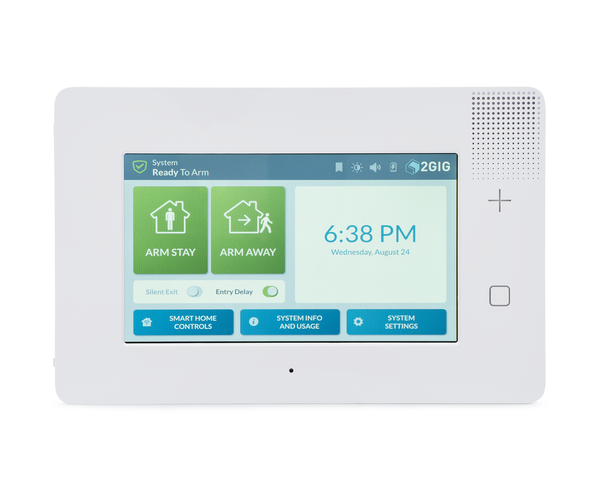
| 2GIG GC2 | 1561 | 1111 |
| 2GIG GC3 | 1561 | 1111 |
| Qolsys | 1111 | 1234 |
| Interlogix Simon XT | 4321 | 1234 |
| Interlogix Simon XTi & XTi-5 | 4321 | 1234 |
| DSC Impassa | 5555 | 1234 |
Use the information in the table above to set the codes in your panel back to their default values. If you don't see your panel listed, you can likely find the information you need with a quick online search. Performing this process is the single most helpful thing you can do for the new homeowner when it comes to the alarm system!
Ms. Manners Says: Leave Behind Good Notes
Any information you know about your alarm system, such as the manufacturer and model, the default installer code, and the default master code - each of which hopefully you have programmed into your panel by this time - will be helpful for the new homeowner. A list of zone numbers and their descriptions is also very much appreciated by a new homeowner. Leave them a note, tucked behind the keypad, or on a kitchen counter. Give them the sequence of keys to enter to disarm the system, or better yet, if you have the opportunity, show it to them, and then leave them a note to back up your demonstration.
If you're willing, leave them your contact information so they can contact you in the event that something unforeseen comes up. This is particularly important if your system is somewhat complex and has multiple home automation features integrated with it. I promise the last thing the new homeowner wants to do is bother you if they can avoid it. Everyone at Alarm Grid has talked with a frantic new homeowner who never even considered contacting the prior homeowner. It's usually something we suggest if we're unable to assist.
Fortunately, in most cases, we are able to assist, and we are happy to do so. This is just one of the many ways we make new friends here at Alarm Grid! I hope that anyone who is preparing to move out of a home and leave behind an alarm system will read this and use these suggestions to prepare.
If you happen to be moving into a home that already has an alarm system, and perhaps the previous homeowner didn't read this post, feel free to reach out to us. We're here Monday - Friday from 9:00 am to 8:00 pm Eastern Time. You can reach us via email, or by calling 888-818-7728.

 If we're looking purely at recording capabilities, the Alarm.com ADC-VDB770 is the clear winner here today, It offers a live recording resolution of up to 1440x1920, though the resolution will often be turned down to prevent any lags or disruptions on a live camera stream due to upload bandwidth requirements. Recorded clips are also available in 1440x1920 resolution. The camera's field of view (FoV) is also quite impressive, at 150° Vertical, 115°


 Before we discuss the issue itself, we will first cover some terminology to ensure that everyone is on the same page. Many Honeywell VISTA Alarm Panels come in both SIA and non-SIA variants. For example, there is the
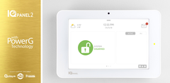
 Before we give our three (3) tips to follow, let's make sure we're all on the same page by explaining what Supervision Trouble normally refers to. Supervision Trouble occurs when a